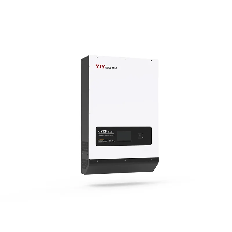
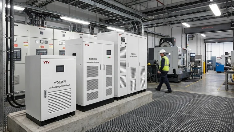
An IGBT static voltage stabilizer design is the better fit when your sensitive load needs fast, stepless, high-precision correction; servo or relay stabilizers remain practical when your load is less sensitive and you can accept slower mechanical movement or stepped regulation.
If your CNC line, medical system, laboratory equipment, telecom rack, or critical automation process cannot tolerate voltage drift, your decision is not simply “advanced versus traditional.” It is about response speed, output stability, maintenance exposure, proof documents, and the operational risk of choosing the wrong topology.
For the broader technology context, start with YIY’s igbt voltage stabilizer overview, then use this guide to compare IGBT static AVR, servo, and relay options by circuit concept, sizing checks, standards evidence, and procurement risk.
Here’s what you will cover: when conventional stabilizers fall short, how DSP/PWM static regulation works, which specification checks decide the right model, and what you should verify before you approve a supplier shortlist.
Why Do Servo or Relay Stabilizers Fall Short for Sensitive Industrial Loads?
Your servo or relay stabilizer can regulate voltage, but it may fall short when your load needs fast, continuous correction without mechanical delay or stepped output changes.
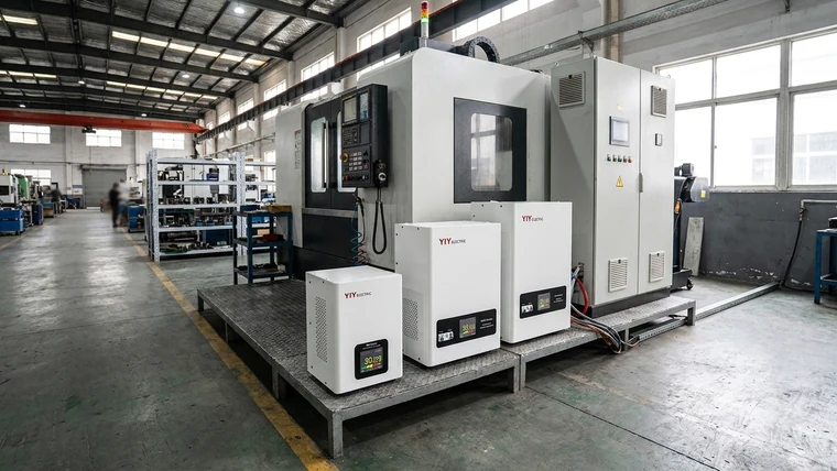
Servo stabilizers use a motor-driven autotransformer to correct voltage. That design is proven for many industrial applications, but it introduces moving parts such as a servo motor, carbon brushes, sliding contacts, and mechanical assemblies. For your site, that means the protection strategy depends not only on kVA rating, but also on service intervals, brush wear, contact condition, response speed, and how often the input voltage fluctuates.
Relay stabilizers are simpler. They switch between transformer taps in discrete steps, which can be acceptable for basic utility loads, general lighting, small appliances, or budget-sensitive use. The tradeoff is that your output correction is not truly stepless. If your connected equipment needs tight voltage continuity, precise measurement, stable process control, or low disturbance during correction, relay tap switching becomes a limitation.
| Stabilizer type | Correction style | Maintenance profile | Best-fit load | Main watch-out for you |
|---|---|---|---|---|
| Relay AVR | Discrete tap switching | Low to moderate | General loads, small capacity, budget-sensitive use | Step changes and limited precision |
| Servo stabilizer | Motor-driven autotransformer | Brushes, motor, contact wear | Broad industrial loads with moderate sensitivity | Slower mechanical response and planned service |
| Static AVR / IGBT line conditioner | Semiconductor PWM / stepless correction | No brush or motor wear in the correction path | CNC, medical, telecom, labs, automation, unstable grids | Requires proper sizing, thermal design, and EMC review |
The practical meaning is straightforward: if your load can tolerate small voltage steps and slower correction, relay or servo technology may still be enough. If your load trips, resets, alarms, or produces scrap when voltage moves quickly, you should evaluate a static IGBT topology earlier in the selection process.
Standards help you define the electrical environment. The official IEC 60038 standard voltage definitions provide a reference for standard supply voltages, while IEC 61000-4-11 voltage dip and interruption immunity testing helps frame voltage dip and short interruption behavior. For you, these standards do not automatically select a stabilizer, but they give your RFQ and acceptance review a clearer language for nominal voltage, disturbance conditions, and test expectations.
Competitor context is useful here. Some regional suppliers visibly emphasize servo stabilizers and isolation transformers, which can be valid choices where mechanical regulation is acceptable.
When your comparison includes digital PWM, DSP control, and IGBT switching, your evaluation should shift from “can it regulate?” to “can it regulate fast enough, smoothly enough, and with enough evidence for this load?” For simpler low-capacity or budget-driven applications, a relay voltage stabilizer may still be appropriate, but it should not be treated as equivalent to a static design for precision-critical equipment.
What Makes an IGBT Static Design a Stronger Fit for Precision Voltage Regulation?
Your strongest reason to choose an IGBT static design is the combination of fast electronic correction, stepless output control, tighter voltage accuracy, and no brush or motor wear in the correction path.
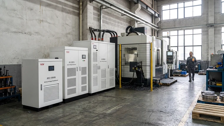
A static voltage stabilizer, IGBT voltage regulator, static AVR, or industrial line conditioner uses semiconductor switching instead of a motor-driven autotransformer. Because the correction path does not rely on carbon brushes, servo motors, or relay tap contacts, your maintenance exposure can be lower than with mechanical regulation, especially at sites with frequent voltage movement. This does not remove the need for inspection, ventilation checks, or protection testing, but it removes a common mechanical wear mechanism.
The core advantage is stepless correction. DSP control and PWM switching can adjust the output continuously rather than jumping between relay taps or waiting for a motor to reposition. YIY product documentation specifies ±0.5% output precision for this IGBT product class. In practical terms, your CNC controller, medical electronics, laboratory instrument, telecom rack, or automation line sees a narrower voltage window during operation than it would with a looser regulation design.
| Decision point | IGBT static AVR | Servo stabilizer | Relay stabilizer |
|---|---|---|---|
| Output correction | Stepless PWM correction | Continuous but mechanically driven | Stepped tap correction |
| Response behavior | Electronic switching | Motor movement limits response | Relay switching limits granularity |
| Wear path | No brush or motor wear in correction path | Brushes, motor, contacts | Relay contacts |
| Precision fit | Strong for sensitive loads | Good for moderate sensitivity | Basic regulation |
| Procurement concern | Verify thermal, EMC, bypass, and protection evidence | Verify serviceability and brush/contact maintenance | Verify tap range and step tolerance |
For your selection, this means you should not compare topology only by purchase price. Compare the cost of false trips, process instability, service visits, production stops, and unclear fault diagnosis. If downtime or product quality risk is high, the higher-specification static design can be easier to justify.
YIY’s differentiation is strongest when your sourcing process needs engineering support beyond a catalog match: IGBT/digital precision, OEM/ODM scope, IEC-oriented documentation, and comparison-based selection across IGBT, servo, and relay options. YIY supports voltage stabilizer solutions from 0.5KVA to 3000KVA with global OEM/ODM manufacturing scope. For you, that means the capacity conversation can cover small controlled loads, larger plant-level systems, and custom site conditions rather than one fixed product tier.
How Does the DSP, PWM, and Double-Conversion Topology Work?
Your IGBT static AVR works by sensing the input, calculating a correction command through DSP or microcontroller logic, driving IGBT switching through PWM, and delivering a stabilized AC output through filtering, transformer, feedback, and protection stages.
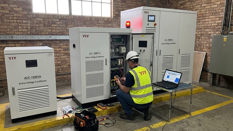
A simplified static voltage stabilizer circuit diagram usually looks like this:
Input AC
 ↓
Input sensing: voltage, frequency, phase, fault status
 ↓
Rectification / DC link or equivalent static conversion stage
 ↓
DSP / microcontroller control logic
 ↓
IGBT PWM switching stage
 ↓
Transformer + output filter
 ↓
Output voltage monitoring
 ↓
Protection logic: overload, short circuit, high/low voltage, bypass, alarms
When you search for an IGBT based voltage stabilizer circuit diagram, a static voltage stabilizer IGBT PWM circuit, or an IGBT based PWM static voltage stabilizer, you are usually looking for this functional power path rather than a proprietary component-level schematic. A responsible supplier can explain the control architecture, protection philosophy, bypass path, alarm logic, and power flow. Detailed gate-drive values, DSP algorithms, PCB layouts, and thermal design rules are usually treated as engineering IP.
In a double-conversion approach, the incoming AC is converted into a controlled intermediate stage, often described as an AC→DC→AC path, before being rebuilt into regulated AC output. That topology helps isolate your downstream equipment from unstable input behavior. The practical result is not just “cleaner voltage” as a marketing phrase; it means your load is less exposed to input swings, provided the stabilizer is correctly sized and the disturbance remains within its design window.
| Function | What it does | What it means for your site |
|---|---|---|
| DSP / microcontroller | Calculates correction from live voltage feedback | Faster control decisions than mechanical regulation |
| PWM | Modulates IGBT switching pulses | Smooth correction instead of tap jumps |
| IGBT bridge | Executes high-speed power switching | No brush, motor, or relay-contact wear in the correction path |
| Filter / transformer | Shapes and conditions output voltage | Better output stability for sensitive downstream equipment |
| Protection logic | Trips, alarms, bypasses, or limits operation | Clearer fault handling and safer recovery |
Protection should not be an afterthought. For dusty, humid, hot, or unstable-grid sites, you should check cabinet ventilation, temperature rise, conformal coating options, enclosure/IP expectations, surge coordination, bypass logic, alarm outputs, event logs, and whether monitoring can connect with PLC, SCADA, BMS, or maintenance workflows. If you skip these items, a technically correct stabilizer can still become a downtime risk because your operators cannot see what happened during a fault.
Which Specification Checks Decide the Right Stabilizer Type and Size?
Your right stabilizer type and size are decided by measured load behavior, actual input-voltage range, startup current, phase configuration, environment, sensitivity, bypass needs, and proof documents—not by nominal kVA alone.
Start with the nameplate only as a rough reference. Then validate your real running current, starting current, power factor, voltage sag/swell history, load diversity, and future expansion plans. If your project is three-phase, use a structured 3 phase main line stabilizer sizing process so the final model reflects phase configuration, imbalance, startup behavior, and site voltage data.
If you need a broader decision framework across technologies and load types, this industrial voltage stabilizer selection guide can help you build the shortlist from measured conditions rather than nominal capacity alone.
| Check | Why it matters | If you skip it |
|---|---|---|
| Total connected load vs running load | Connected kVA shows installed demand; running load shows what your AVR usually carries. This helps you avoid both undersizing and blind oversizing. | Nuisance overload trips or unnecessary capital cost |
| Power factor and nonlinear loads | Low power factor, VFDs, rectifiers, UPS inputs, and harmonic-rich loads increase current stress. Your stabilizer may need a higher current rating than the simple kW number suggests. | Hot components, unstable correction, distorted output |
| Motor starting current | Motors can draw several times rated current during startup. Your AVR must tolerate short peaks without false tripping. | Trips during startup and production interruption |
| Measured min/max input voltage | Your lowest sag and highest swell matter more than the utility’s nominal voltage. This determines whether a standard or custom input range is needed. | Correct kVA, wrong voltage window |
| Fluctuation speed | Fast dips favor static IGBT regulation; slower movement may allow servo designs. | Sensitive machines may still fault after installation |
| Phase imbalance and neutral quality | Three-phase imbalance affects correction strategy, protection, and downstream equipment health. | Overheating, nuisance alarms, poor load protection |
| Generator, solar, UPS, and bypass interaction | Alternative sources can shift frequency, waveform, and transfer behavior. Your bypass logic should be defined before purchase. | Transfer faults, backfeed risk, unclear recovery path |
| Ambient temperature, altitude, ventilation | Heat and altitude reduce cooling margin. Your supplier should confirm derating rules. | Thermal alarms and shortened component life |
| Dust, humidity, enclosure/IP needs | Dusty, humid, or corrosive environments may require filters, heaters, conformal coating, sealed cabinets, or higher IP protection. | Failures caused by environment rather than load |
| Documentation and standards | Align voltage assumptions with IEC 60038, disturbance discussions with applicable IEC 61000 tests, and quality expectations with ISO 9001:2015 quality management systems. Data verified against official standards pages as of 2026 Q2. | Weak FAT approval, unclear compliance, warranty disputes |
After these technical numbers, the practical interpretation is simple: your stabilizer has to survive the worst reasonable site condition, not just the average condition. A model that looks correct at nominal voltage can still fail your application if startup peaks, heat, harmonic current, or voltage sag exceed its real operating margin.
For approval-heavy projects, request the supplier’s nameplate data, single-line diagram, block diagram, factory acceptance test report, protection settings, alarm list, bypass description, and monitoring options. Event logging, remote alarms, and PLC/BMS/SCADA compatibility help your maintenance workflow identify whether a trip came from grid sag, overload, overheating, phase loss, or bypass operation.
If exact DSP algorithms, component-level PWM stage details, DC-link design, response behavior, or thermal design numbers affect your technical approval, ask the supplier directly. If those details are proprietary, request performance evidence instead: correction range, output tolerance, overload curve, temperature limits, EMC documentation, and FAT test records.
What Final Procurement Checks Should You Complete?
Your final approval should confirm design fit, prove that static IGBT regulation is necessary for the load, and validate sizing against measured site data.
Treat this as your last risk gate before purchase. A wrong stabilizer choice can create nuisance trips, unstable equipment, warranty disputes, brush maintenance, unclear bypass behavior, and avoidable downtime.
| Check | Why it matters | If you skip it |
|---|---|---|
| Load sensitivity review | Confirms whether your process actually needs fast, stepless correction and tight output tolerance | You may over-specify a simple load or under-protect a critical one |
| Input-voltage evidence | Confirms the stabilizer’s correction range matches real sag and swell data | The unit may be correctly rated but unable to regulate at your site |
| Startup and overload curve | Confirms short-duration peaks can be tolerated | Motors, compressors, or drives may trip the stabilizer at startup |
| Bypass path | Confirms safe operation during fault, maintenance, or overload conditions | Operators may improvise unsafe recovery steps |
| Alarm and monitoring logic | Confirms your maintenance team can diagnose faults quickly | Downtime becomes harder to explain and prevent |
| Cooling and enclosure review | Confirms temperature, dust, humidity, and cabinet clearance are acceptable | Heat or contamination can shorten component life |
| FAT and documentation package | Confirms the quoted model matches performance claims | Approval becomes subjective and warranty discussions become harder |
For your RFQ, include minimum and maximum input voltage, load list, running current, startup current, power factor, harmonic sources, phase configuration, bypass requirement, enclosure/IP needs, ventilation constraints, dust or humidity exposure, and monitoring expectations. Then verify the final model by matching the supplier’s single-line diagram, protection settings, and capacity margin against your electrical drawings.
If your project is moving from technical comparison to procurement shortlist, use a structured checklist such as this guide to compare before buying a voltage stabilizer so you can keep proof points, tradeoffs, and supplier responses in one review process.
Frequently Asked Questions
What Should You Know About a Static Voltage Stabilizer Circuit Diagram?
A static voltage stabilizer circuit diagram usually shows the functional power path, not the supplier’s proprietary component-level design. You should expect blocks for input sensing, rectification or static conversion, DSP or microcontroller control, IGBT PWM switching, transformer/filter stage, output feedback, bypass, and protection logic. Use the diagram to confirm architecture, fault handling, and maintenance visibility—not to reverse-engineer gate-drive details or firmware.
Can an IGBT Based Voltage Stabilizer Circuit Diagram Be Used for Supplier Evaluation?
Yes, a block or single-line diagram helps you compare suppliers, as long as it comes with test evidence. Ask the supplier for a block diagram, single-line diagram, protection list, alarm logic, bypass path, and FAT test report. Then cross-check those documents against your load schedule, input-voltage range, enclosure needs, and approval file so the drawing matches the quoted model.
What Should Be Checked in a Static Voltage Stabilizer IGBT PWM Circuit Before Purchase?
You should check the control method, protection coverage, thermal margin, and output accuracy. Verify the DSP/PWM control description, overload curve, short-circuit protection, high/low-voltage limits, bypass operation, cooling design, and alarm outputs. For compliance-heavy projects, request IEC/ISO-related documentation and compare nominal voltage assumptions with the official IEC 60038 voltage definitions.
When Is an IGBT Based PWM Type Static Voltage Stabilizer Worth the Higher Specification?
This topology is worth the higher specification when downtime, voltage drift, servo response delay, or relay step changes can disrupt your sensitive equipment. It fits CNC machines, medical systems, test labs, telecom racks, automation lines, and unstable-grid sites better than basic relay or slower mechanical options. Before approving the upgrade, compare the equipment maker’s allowable input range with the stabilizer’s output tolerance, correction range, overload curve, and FAT results.
Final Thoughts
Your best fit is an IGBT static AVR when sensitive industrial loads need fast, stepless, high-precision correction and the cost of voltage-related disruption is high. Servo or relay stabilizers can still make sense when your load is less sensitive, your budget is constrained, and slower or stepped regulation will not create process risk.
For your decision, start with load sensitivity and downtime risk, then check measured voltage behavior, startup current, power factor, environment, bypass needs, monitoring, and compliance evidence. The goal is not to over-specify every site. It is to avoid choosing a cheaper topology that later creates nuisance trips, process interruptions, brush maintenance, or unclear fault diagnosis.
A practical next step is a quick-fit comparison review. You can shortlist IGBT static AVR, servo, and relay options against your application tolerance, proof documents, and approval criteria before you prepare detailed logs or internal load data. If you want a conservative second opinion, ask YIY for a comparison-based consultation focused on tradeoffs, proof points, and shortlist criteria.
About YIY
Zhejiang Yiyen Holding Group Co., Ltd. (YIY) is a professional voltage stabilizer manufacturer with 16+ years of experience. With a 30,000sqm modern facility and an annual production capacity of 1,000,000+ units, YIY products are exported to 130+ countries. YIY provides OEM/ODM customization services and is ISO 9001:2015 certified, supporting stable and reliable voltage protection solutions for global customers.
Contact Us
Email: yiyen@yiyen.com
Phone/WhatsApp: +86 13587452904
Website: https://www.yiyavr.com/