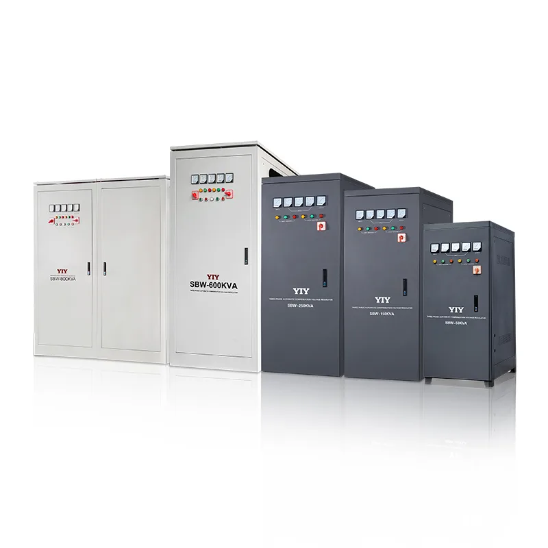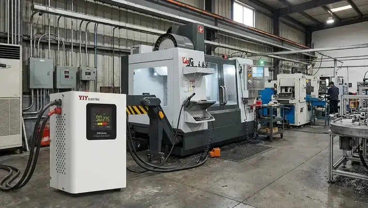
Unpredictable utility grids don’t just cause brownouts; they trigger cascading downtime across CNC cells, automated manufacturing lines, and critical infrastructure. The financial exposure from undersized or mismatched protection routinely outpaces the initial hardware investment, turning a routine specification into a high-stakes operational decision. Selecting a 50 kva voltage stabilizer demands strict alignment between actual load dynamics, local grid variance, and corrective precision.
This evaluation framework outlines the technical checkpoints engineering and procurement teams must validate before issuing an RFQ. We will break down stabilization topologies, map exact sizing formulas, audit mandatory certification thresholds, and flag the environmental variables that dictate long-term field performance.
What a 50 kVA Voltage Stabilizer Actually Does in Industrial Settings
An industrial-grade automatic voltage regulator (AVR) actively corrects utility instability, shielding downstream infrastructure from destructive sags, transient surges, and prolonged brownouts. Instead of exposing your distribution panel to raw grid variance, the unit continuously samples primary line conditions and dynamically adjusts the output to maintain strict tolerance bands.
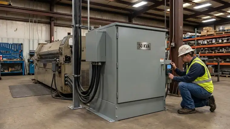
When evaluating a Servo Voltage Stabilizersservo voltage stabilizer for your facility, understanding how these operational load envelopes interact with medium-power installations is the first step toward reliable uptime. A 50 kVA rating specifically targets medium-power installations sustaining 37.5 kW to 40 kW of continuous steady-state load. Because apparent power must accommodate both real work and reactive magnetization, engineers factor a typical 0.75–0.8 industrial power factor to prevent transformer overheating. Layering a standard 20 percent safety margin on top of these peak demands guarantees the copper windings never operate at continuous thermal duty limits. Procurement teams should always verify nameplate kVA against actual running current before finalizing RFQs.
Core Topologies at Capacity
Three regulation architectures dominate purchasing decisions at this scale. Servo-controlled systems offer the strongest balance for factories, utilizing a motorized variable autotransformer assembly to achieve ±1–2 percent accuracy with rapid electromechanical response. While a standard Relay Voltage Stabilizersrelay voltage stabilizer switches discrete fixed taps to handle wide voltage drift, its coarser ±5–8 percent tolerance generally suits non-critical lighting or basic compressor banks rather than precision electronics. Solid-state IGBT units bypass moving parts entirely, delivering microsecond pulse-width correction and ±0.5 percent precision where zero-downtime is mandatory. Choosing the right topology requires weighing correction speed against long-term maintenance cycles. This capacity effectively avoids the heavy mechanical wear of multi-megawatt systems while significantly outperforming lightweight commercial relays.
For a deeper dive into how correction architectures perform at specific capacity tiers, review our Stabilizer Voltage Regulator Comparisondetailed relay vs servo vs IGBT comparison.
Equipment Protection in Practice
This corrective bandwidth directly determines which capital assets survive daily electrical stress. CNC milling centers require stable phase voltages to maintain spindle synchronization and eliminate sensitive drive board faults. Medical imaging consoles and high-capacity commercial HVAC chillers demand unbroken sine wave integrity to prevent motor lockups and refrigerant cycling errors.
Procurement teams must align the selected architecture with the specific voltage sensitivity of downstream electronics, which often requires clarifying the Voltage Stabilizer Vs Voltage Protector Guidevoltage stabilizer vs protector differences when mapping downstream defense layers against specific grid anomalies. While protectors handle catastrophic spikes, stabilizers manage continuous fluctuation. Furthermore, site engineers should integrate these corrective systems alongside established ElectricalOSHA electrical safety standards to ensure circuit isolation requirements and arc-flash mitigation protocols fully protect heavy machinery and personnel. By standing between volatile grid feed and precision manufacturing auxiliaries, the stabilizer converts unpredictable utility behavior into reliable operational continuity.
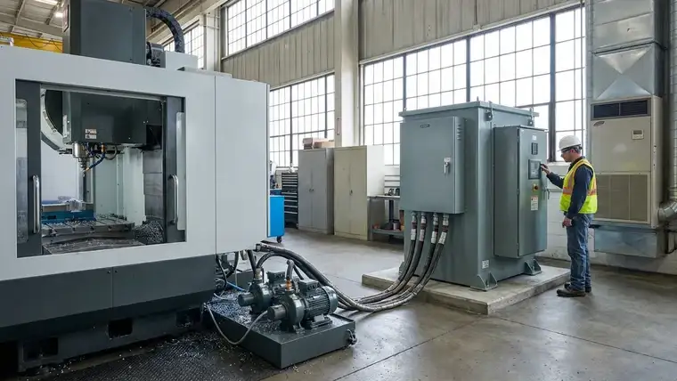
Key Technology Choices: Servo vs. Relay vs. IGBT for 50 kVA Loads
Procurement teams must align stabilization topology with downstream load sensitivity before issuing an RFQ. At the 50 kVA tier, three architectures dominate the industrial market, each presenting distinct precision, maintenance, and uptime trade-offs.
Servo Control: The Default Industrial Standard
Servo-driven stabilizers dominate medium-power factory floors by delivering ±0.5–3% output regulation with ≤1–2 second correction speeds. A motorized carbon brush continuously traverses a variable autotransformer winding, enabling seamless micro-adjustments that absorb continuous voltage drift without electrical stress. This electromechanical architecture strikes the optimal balance between operational precision and long-term component durability for CNC centers and automated assembly lines.
IGBT Solid-State: Ultra-Precision for Mission-Critical Systems
Insulated gate bipolar transistor (IGBT) modules bypass moving parts entirely, utilizing rapid electronic switching to guarantee ±0.5% ultra-precision across all operating conditions. Microsecond-level response times instantly neutralize severe sags and transient harmonics, shielding highly sensitive medical imaging arrays and precision semiconductor fabrication tools. The elevated initial capital outlay is rapidly offset when facility downtime directly correlates with catastrophic production stoppages or high-value material scrap.
| Topology | Voltage Precision | Response Time | Ideal Use Case | Maintenance Requirements |
|---|---|---|---|---|
| Servo | ±0.5% to 3% | ≤1–2 Seconds | General manufacturing, CNC, automated lines | Annual carbon brush inspection, mechanical cleaning |
| Relay | ±5% to 8% | ≤50ms | Lighting, non-critical HVAC, basic resistive loads | Contactor replacement every 3-5 years, thermal checks |
| IGBT | ±0.5% | Microseconds | Medical imaging, labs, semiconductor fabs | Firmware updates, cooling fan replacement, capacitor checks |
Facility uptime risk ultimately dictates the correct topology selection. When the financial exposure of unplanned machinery failure outpaces hardware premiums, investing in high-fidelity servo or solid-state architectures guarantees a lower lifetime cost of operation.
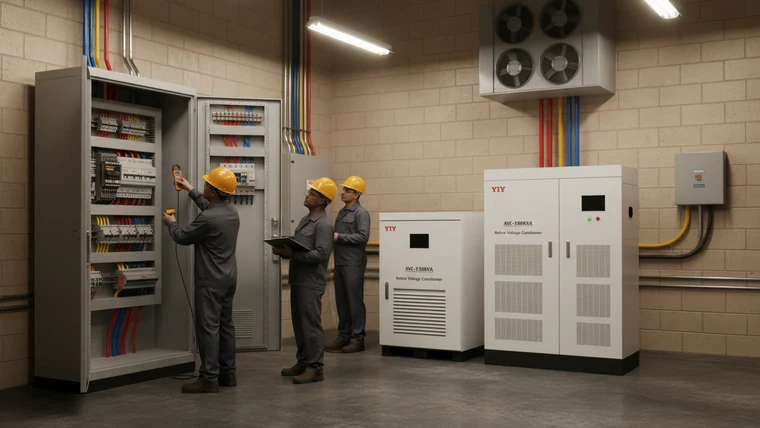
How to Calculate Load Requirements and Size a 50 kVA Unit Correctly
Step-by-Step Load Inventory
Begin by compiling a comprehensive load inventory that captures the running watts and apparent power of every connected asset. Convert real power (kW) to apparent power (kVA) by dividing by the facility’s operational power factor, typically between 0.75 and 0.80. Summing these baseline figures establishes your true continuous demand, a core principle of the recommended Voltage Stabilizer Industrial Technical Guideindustrial load sizing methodology that ensures downstream busbars never exceed thermal limits before protective overhead is applied.
Applying the Safety Multiplier
Raw running totals never account for harmonic distortion, line voltage drop, or long-term thermal stress. Multiply your calculated steady-state kVA by a conservative 1.2–1.3x factor to buffer for efficiency losses and reserve immediate headroom for planned automation expansion. This deliberate over-specification prevents core saturation, directly anchoring your procurement baseline when requesting a formal voltage stabilizer 50 kva price from OEMs.
Handling Motor Inrush and Transformer Surges
Steady-state calculations fail the moment heavy electromechanical loads energize. Direct-on-line (DOL) starts routinely pull 500–800 percent of rated current, demanding instantaneous peak kVA headroom that undersized units cannot sustain without internal breaker trips. Upgrading to star-delta starters or integrating variable frequency drives (VFDs) dramatically flattens the startup curve, while accurately calculating control transformer inrush dictates your true momentary demand envelope. Always cross-reference these transient peaks with vendor response specifications when analyzing a 50 kva servo voltage stabilizer price.
Phase Balancing and Site Derating
Uneven phase loading generates negative sequence currents that rapidly overheat windings and degrade insulation over time. Measure line currents at the main distribution board and systematically redistribute single-phase auxiliaries until phase asymmetry remains strictly below 10 percent. Validating these electrical parameters requires a strict understanding of 3 Phase Voltage Stabilizer 20kva Type Selection3-phase balancing and derating factors to prevent costly warranty disputes related to misapplied capacity ratings. High-ambient facilities or tightly sealed electrical rooms also require licensed site engineers to apply strict environmental derating curves before finalizing the hardware specification.
Compliance, Certification, and Input Tolerance Standards
Mandatory certifications separate compliant industrial units from grey-market alternatives. Engineering teams must verify documented adherence to international electrical standards to guarantee long-term reliability and avoid costly retrofitting or customs rejections during global deployment.
Global Voltage Standards and Tolerance Windows
Units must strictly align with the 6952IEC 60038 standard voltage parameters to ensure cross-border compatibility. This framework defines a standard ±10% input voltage tolerance window, allowing the stabilizer to correct severe grid fluctuations across diverse regions without triggering internal fault trips. Operating outside these certified bands compromises downstream equipment and voids manufacturer warranties.
Manufacturing and Environmental Certifications
ISO 9001:2015 certification validates consistent manufacturing processes and rigorous traceability across every production batch. Adhering to 62085.htmlISO 9001 manufacturing standards guarantees buyers that their supplier maintains sustainable, defect-controlled assembly lines. When combined with ISO 14001 environmental management requirements, this dual compliance significantly reduces field failure rates and simplifies lifecycle maintenance planning.
Regional Export Markings
CE marking remains a non-negotiable requirement for EU exports, demonstrating conformity with strict health, safety, and performance directives. Manufacturers must also account for regional testing variations, as local grid harmonics and surge protection mandates fluctuate significantly across international markets. Procurement teams should always request third-party test reports that mirror actual site conditions before signing purchase orders.
Critical Protection Features
Essential protection mechanisms dictate how equipment survives extreme electrical anomalies. Over/under-voltage cutoff safeguards actively disconnect the load the moment input drifts beyond safe operating thresholds. Auto-alarm systems immediately notify facility managers when the unit detects sustained input outside its rated range, enabling proactive dispatching. Integrated short-circuit safeguards isolate internal faults instantly, preventing catastrophic arc flashes and minimizing collateral damage to expensive production machinery.
Manufacturer Capabilities, Site Conditions, and Implementation Steps
Environmental Matching and Cooling Selection
Match thermal management directly to on-site ambient temperature, airborne particulate density, and facility ventilation constraints. Standard forced-air architectures demand unobstructed perimeter clearance for passive convection, making them ideal for climate-controlled electrical distribution rooms. Conversely, oil-immersed transformers deliver superior thermal inertia and arc suppression in extreme-heat foundries or poorly ventilated industrial sheds, provided secondary catchment basins strictly comply with local environmental spill regulations.
Global Supply Chain vs. Regional Assemblers
Procurement teams must rigorously evaluate vendor logistics alongside baseline hardware pricing to guarantee long-term operational continuity. While regional distributors frequently promise shorter initial delivery windows, established multinational manufacturers maintain localized spare parts hubs across 130+ countries, drastically reducing emergency mean time to repair. Prioritize suppliers offering true OEM/ODM engineering flexibility to customize IP ratings or Modbus-RTI communication protocols for seamless SCADA integration across multi-site facilities.
Foundation Stability and Bypass Architecture
Strict physical mounting and circuit isolation prerequisites dictate equipment longevity long before initial utility energization. Verify reinforced concrete pad stability with seismic dampening rated for continuous servo-motor harmonic vibrations, then precisely calculate incoming copper cross-sections using IEC thermal derating charts to prevent cable saturation. Always integrate an external maintenance bypass isolator upstream of the main breaker to guarantee zero-downtime operations during scheduled carbon-brush replacements or critical firmware patches.
Commissioning Protocols and Vendor Differentiation
Final site acceptance demands rigorous validation rather than simple power-on sequencing, ensuring hardware performance aligns precisely with procurement specifications. Licensed engineers must verify zero-load waveforms, enforce strict phase alignment, and execute simulated overload cutoff tests tailored to the selected topology. Transparent manufacturing lead-times paired with dedicated engineering consultation support effectively eliminate integration bottlenecks and establish clear accountability during complex industrial deployments.
Frequently Asked Questions
What should buyers evaluate before choosing a 50 kVA voltage stabilizer?
Prioritize stabilization topology, input voltage tolerance, and thermal management. Servo-driven units deliver ±0.5–3% accuracy for continuous industrial drift, while solid-state IGBT modules guarantee ±0.5% precision for zero-downtime medical or semiconductor operations. Always match the enclosure IP rating to facility particulate density and confirm the acceptable input window aligns with local grid variance.
How should a 50 kVA voltage stabilizer be sized for mixed loads?
Convert real power (kW) to apparent power (kVA) using a 0.75–0.80 industrial power factor, then multiply by a 1.2–1.3 safety buffer to account for harmonic distortion. Crucially, map direct-on-line motor inrush currents that can spike 500–800 percent above steady-state demand. Maintain phase asymmetry below 10 percent to prevent premature winding overheating.
Which international certifications verify compliance for heavy-duty export?
Require documented ISO 9001:2015 and ISO 14001 manufacturing compliance as baseline quality benchmarks. CE marking remains mandatory for European markets, while IEC alignment ensures the hardware safely corrects ±10 percent input fluctuations across diverse utility grids. Procurement teams should always demand third-party test reports that mirror actual site conditions before finalizing orders.
Final Thoughts
Specifying a 50 kva voltage stabilizer is an operational risk calculation, not merely a procurement checkbox. By methodically validating topology trade-offs, accurate load scaling, and certified compliance standards, you eliminate the hidden financial exposure of undersized protection. A mismatched unit inevitably triggers cascading production downtime or premature thermal failures, quickly eroding any initial hardware savings.
Procurement leads must treat vendor proposals as engineering validation checkpoints rather than final purchasing decisions. To guarantee continuous facility operations, compile your complete load inventory, motor inrush currents, and site environmental constraints. Submit these parameters directly to our custom engineering consultation form for a verified sizing review, ensuring your final deployment aligns exactly with your application’s operational tolerances and budget parameters.
About YIY
Zhejiang Yiyen Holding Group Co., Ltd. (YIY) is a professional voltage stabilizer manufacturer with 16+ years of experience. With a 30,000sqm modern facility and an annual production capacity of 1,000,000+ units, our products are exported to 130+ countries. We provide OEM/ODM customization services and are ISO 9001:2015 certified, committed to delivering stable and reliable voltage protection solutions to global customers.
Contact Us
Email: yiyen@yiyen.com
Phone/WhatsApp: +86 13587452904
Website: https://www.yiyavr.com/
If you found this article helpful, contact us for a sizing review or customized solution.
Selection Notes: Why 50 KVA Is a Transition Tier
Fifty KVA is rarely a “simple mid-size quote”. It is the point where many projects stop behaving like workshop loads and start behaving like feeder or sub-panel decisions. That makes the 50 KVA tier especially prone to wrong-model quoting when buyers compare only price and precision but ignore installation role.
- Stay in the 50 KVA tier: when the stabilizer serves one defined process cell, workshop line, or sub-panel with known growth limits.
- Step to plant-scale review: when the quote is already protecting multiple production zones or a shared feeder that will expand within the next budget cycle.
- Model-family distinction: PRO-3 / SVC-3 make sense for standard three-phase workshop protection; PWR-3 matters when the site has weak-grid input constraints; SBW-class products are better once the project becomes a true central-feeder installation.
- Commercial checkpoint: ask whether the buyer wants a “50 KVA machine-protection unit” or a “50 KVA feeder-protection unit” — that single clarification usually changes the shortlist.
Use the 10-25 KVA guide when the project is still workshop-scale, and the 200-500 KVA guide when the quote is clearly moving toward plant-level distribution.