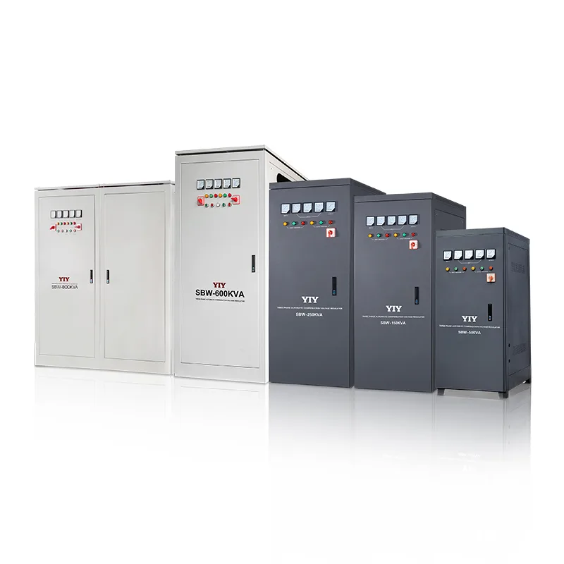
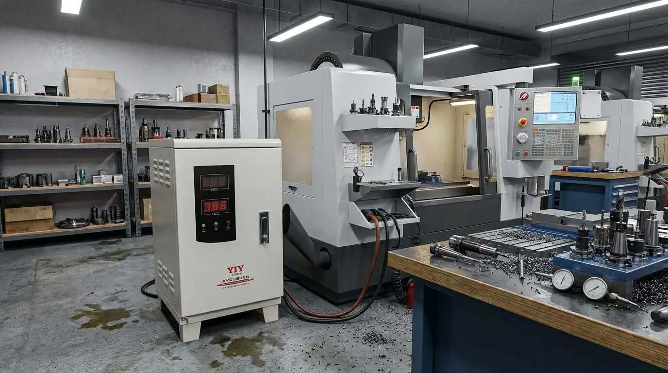
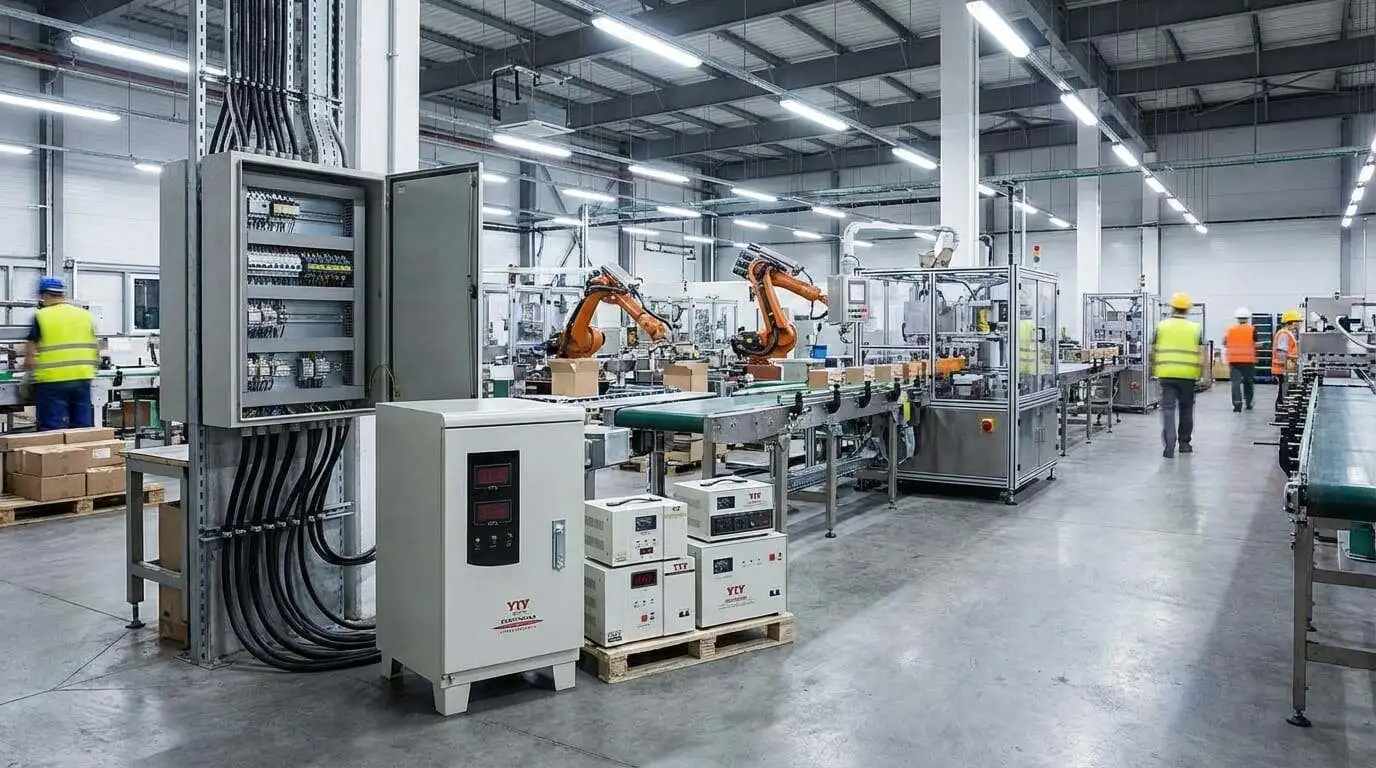
A 10–25 KVA three phase voltage stabilizer protects the loads too heavy for a single-phase wall unit yet too light to justify a 100+ KVA cabinet: CNC machining cells, automated packaging lines, commercial HVAC sections, communication racks, and workshop distribution panels.
These are the loads where a sizing mistake does not just trip a breaker — it halts a production shift.
Three-phase stabilizers in this range operate at 380 V / 400 V line-to-line and regulate all three phases independently. That distinction matters. A single-phase AVR cannot correct phase imbalance, and phase imbalance is precisely the failure mode that damages three-phase motors and drives. If the facility runs three-phase equipment, the stabilizer must be three-phase.
This guide walks plant engineers and procurement teams through the complete selection process: capacity calculation with motor-inrush correction, technology comparison (servo, relay, IGBT), real-world sizing examples, pricing drivers, installation requirements, and YIY’s product matrix for this capacity range.
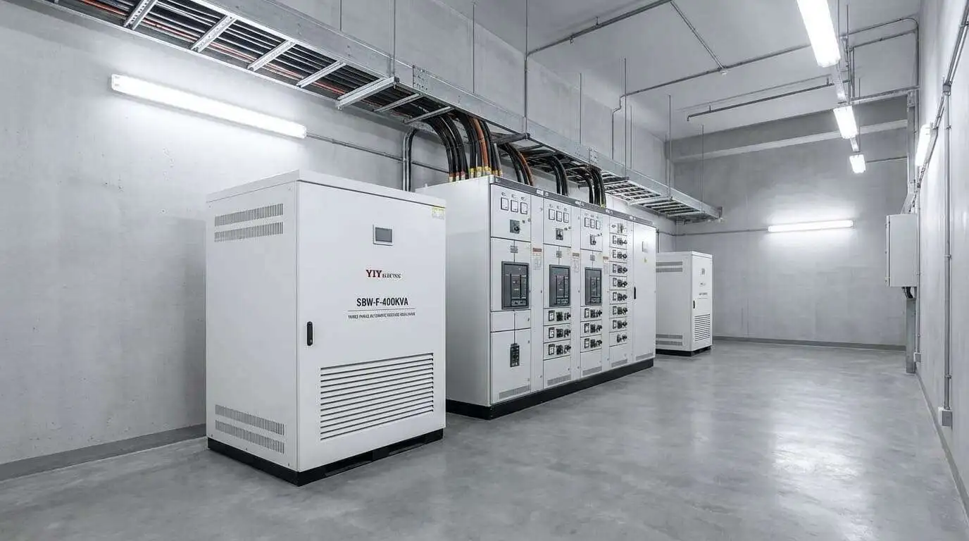
Capacity Sizing for Three-Phase Industrial Loads
Undersizing is the single most common field failure in the 10–25 KVA range, and the cause is almost always the same: the buyer sized for steady-state load and forgot about motor starting current.
The sizing formula:
Required KVA = Total Load (kW) ÷ Power Factor × Safety Margin| Variable | Typical Value | Notes |
|---|---|---|
| Power factor | 0.8 | Standard for mixed industrial loads (motors + electronics) |
| Safety margin | 1.25 – 1.3 | Covers inrush, future load additions, and ambient derating |
The critical correction: motor inrush current. Induction motors — the dominant load type in this capacity range — draw 3–6 times their rated current during the first 200–500 ms of startup. A 5 kW spindle motor rated at 10 A per phase will pull 30–60 A during starting.
If the stabilizer cannot sustain that transient, it trips on overload and the machine never starts.For loads where more than 50 % of total power is motor-driven, replace the 1.25 safety margin with a 2–3 times starting-current factor. This is the rule that separates sizing worksheets from field-proven specifications.
Capacity decision table:
| Load Range (kW) | Select | Typical Application |
|---|---|---|
| up to 8 kW | 10 KVA | Small CNC controller, light automation cell, communication rack |
| 8–12 kW | 15 KVA | Mid-size CNC cell, packaging line section, commercial HVAC zone |
| 12–16 kW | 20 KVA | CNC spindle + auxiliaries, lighting bank, distribution sub-panel |
| 16–20 kW | 25 KVA | Multiple machines on one feeder, workshop panel, small factory main |
| above 20 kW | Step up to 30+ KVA | See the large-capacity industrial guide |
Phase balance matters. Three-phase stabilizers regulate each phase independently. If one phase carries 70 % of the load (common in mixed single/three-phase panels), the stabilizer compensates that phase harder without affecting the other two. A single-phase unit on each phase cannot do this because it has no visibility into the inter-phase relationship.
Input voltage window: Standard three-phase servo stabilizers accept 280–456 V line-to-line (equivalent to approximately 161–263 V per phase). Wide-range models extend down to 240 V L-L (approximately 139 V per phase), covering deep brownout regions in Africa, South Asia, and parts of South America where grid voltage regularly sags below 300 V L-L.
Servo vs Relay vs IGBT for Medium-Capacity Three-Phase Loads
Technology choice determines price, performance, and maintenance schedule. The table below compares all three approaches at three-phase industrial specifications.
| Relay | Servo (PRO-3 / SVC-3) | IGBT (CVCF / AVC) | |
|---|---|---|---|
| How it works | Electromagnetic relays switch between fixed transformer taps | Servo motor drives a variable transformer brush continuously | IGBT power electronics regenerate a clean sine wave from scratch |
| Output precision | ±5–8 % | ±2–3 % (SVC-3) / ±2 % (PRO-3) | ±0.5 % |
| Response time | Near-instantaneous (stepped transitions) | 1–2 seconds (smooth, continuous) | Milliseconds (seamless) |
| Input range (3-phase L-L) | 280–430 V | 240–456 V (model-dependent) | 160–480 V |
| Efficiency | 90–92 % | 95–98 % | 90–95 % |
| Galvanic isolation | No | No | Yes (double-conversion topology) |
| Harmonic distortion | Passes through grid THD | Passes through grid THD | Output THD < 3 % regardless of input |
| Maintenance | Contact inspection every 18–24 months | Carbon-brush check every 12–18 months | Capacitor health monitoring; no wearing parts |
| Relative price | 1x (baseline) | 1.5–2x | 3–4x |
| Best for | Lighting banks, resistive heaters, non-critical loads | CNC machines, motors, panels, packaging lines | Laboratories, medical imaging, semiconductor test, mission-critical data |
Decision shortcut: Roughly 80 % of three-phase industrial loads in the 10–25 KVA range are well served by a servo stabilizer. Servo delivers the precision-to-cost ratio that relay cannot match, and IGBT does not need for standard industrial equipment.
When IGBT is justified:
- Galvanic isolation is a design requirement (medical, laboratory, semiconductor).
- Output regulation tighter than ±1 % is non-negotiable.
- The load is sensitive to harmonics and the grid THD is high.
- Frequency stability matters (generator-fed sites where Hz drifts).
If none of those four conditions apply, servo is the right default — and the budget difference funds the bypass switch and cabling upgrades that actually improve uptime.
Real-World Sizing Examples
Theory is clean. Factory floors are not. The following three examples walk through the sizing process as it actually happens on site, including the inrush correction that textbook formulas often omit.
Example 1: Small CNC Workshop — 10 or 15 KVA?
A three-axis vertical machining center with:
| Component | Rated Power |
|---|---|
| Spindle motor | 5 kW |
| Servo axes (3) | 2 kW total |
| Controller + coolant pump + lights | 1 kW |
| Total steady-state | 8 kW |
Applying the formula:
8 kW ÷ 0.8 (PF) × 1.25 (margin) = 12.5 KVAAt first glance, 10 KVA looks close. But the spindle motor draws 3–4 times rated current during tool-change acceleration, pushing instantaneous demand to 15+ KVA. The correct choice is 15 KVA. Selecting 10 KVA saves money on the purchase order and costs it back in nuisance trips during the first production week.
Example 2: Packaging Line — 15 or 25 KVA?
An automated carton-forming and sealing line:
| Component | Rated Power |
|---|---|
| Conveyor motors (4) | 8 kW total |
| Forming/sealing station motors | 4 kW |
| Control PLCs + HMIs + sensors | 2 kW |
| Total steady-state | 14 kW |
14 kW ÷ 0.8 × 1.3 = 22.75 KVAThe 1.3 margin (instead of 1.25) accounts for six motors starting in sequence during line warm-up. Four of them start within the same 2-second window. The correct choice is 25 KVA. A 20 KVA unit handles steady-state but risks overload during synchronized startup.
Example 3: Commercial Building Sub-Panel — 20 or 25 KVA?
A floor-level distribution panel in a mid-rise office building:
| Component | Rated Power |
|---|---|
| HVAC section (one AHU + 2 FCUs) | 10 kW |
| LED lighting bank | 4 kW |
| Office equipment (PCs, printers, networking) | 2 kW |
| Total steady-state | 16 kW |
16 kW ÷ 0.8 × 1.25 = 25 KVAThe AHU compressor is the largest single motor, and it starts independently from the FCUs. A 1.25 margin is adequate here because only one large motor starts at a time. The correct choice is 25 KVA, sitting right at the edge of calculated demand.
Motor-heavy warning: If more than 50 % of the total connected load is motor-driven, do not use the 1.25 standard margin. Apply a 2–3 times starting-current multiplier to the motor portion of the load, then add the non-motor portion at face value. This single correction eliminates 90 % of field-return sizing errors in the 10–25 KVA range.
What Drives the Price at 10–25 KVA
Two buyers requesting the same 20 KVA three-phase quote can receive numbers that differ by 50 % or more. Here is why.
Primary cost driver: technology type. Servo is 1.5–2 times the price of relay at the same KVA rating. IGBT is 3–4 times. This relationship holds across the entire 10–25 KVA range. Technology selection is the first pricing decision and the largest one.
Secondary cost drivers specific to three-phase units:
| Factor | Impact on Price | Why It Matters |
|---|---|---|
| Phase count | Three-phase costs 2–2.5x more than single-phase at the same total KVA | Three independent regulation circuits, three sets of windings, more complex control board |
| Input voltage range | Wide-range (240–456 V L-L) costs 10–15 % more than standard (280–430 V) | Wider compensation range requires larger toroidal transformers and stronger servo motors |
| Copper vs aluminum winding | Copper adds 15–25 % | Better thermal conductivity and longer life under continuous industrial loads; aluminum is lighter but derated above 40 C ambient |
| IP rating and enclosure | IP54 (dust/splash) adds 10–20 % over IP20 (indoor) | Sealed enclosures, gaskets, and forced-air filtration for factory-floor environments |
| Control features | MCU control (PRO-3) costs more than basic analog control (SVC-3) | Digital monitoring, fault logging, RS485/Modbus communication for SCADA integration |
| OEM customization | Varies widely | Custom branding, non-standard voltage taps, communication protocol integration, special paint, and documentation all add engineering time |
Pricing rule of thumb (2026, FOB China, three-phase, standard IP20 enclosure):
| Capacity | Relay | Servo | IGBT |
|---|---|---|---|
| 10 KVA | $ | $$ | $$$$ |
| 15 KVA | $$ | $$$ | $$$$$ |
| 20 KVA | $$ | $$$ | $$$$$ |
| 25 KVA | $$$ | $$$$ | $$$$$$ |
Exact pricing depends on order quantity, destination certifications, and customization scope. Request a sizing review for a spec-accurate quotation.
Installation and Maintenance Essentials
A correctly sized stabilizer installed incorrectly fails just as fast as an undersized one. The following requirements are specific to the 10–25 KVA three-phase range.
Cable sizing. Match cable cross-section to full-load current, not average load. At 20 KVA and 380 V three-phase, full-load current is approximately 30 A per phase. Undersized cables cause voltage drop between the panel and the stabilizer, which the stabilizer then compensates — wasting regulation range on a problem that thicker cable solves for free.
| Capacity | Approx. Full-Load Current per Phase (at 380 V) | Minimum Cable (Cu, PVC, 30 C ambient) |
|---|---|---|
| 10 KVA | ~15 A | 2.5 mm2 |
| 15 KVA | ~23 A | 4 mm2 |
| 20 KVA | ~30 A | 6 mm2 |
| 25 KVA | ~38 A | 10 mm2 |
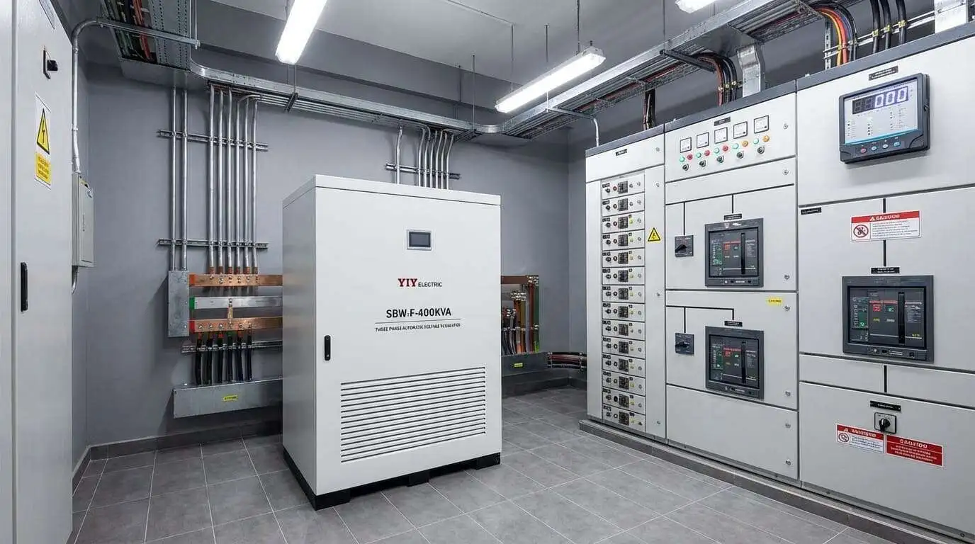
Ventilation. Maintain a minimum of 200 mm clearance on all sides for natural convection. Units rated 15 KVA and above in enclosed electrical rooms require forced ventilation or active exhaust fans. The PRO-3 and SVC-3 series use internal forced-air cooling; ambient temperature above 40 C requires derating by approximately 1.5–2 % per degree.
Bypass switch. For any facility where production cannot stop for stabilizer maintenance, a manual bypass switch is mandatory. The SVC-3 series includes a built-in manual bypass. For the PRO-3, specify the bypass option at order or install an external changeover switch. Bypass allows the load to run directly on mains during brush replacement or inspection without a shutdown.
Grounding. Bond the stabilizer chassis to the same earth bar as the load panel. A separate earth rod for the stabilizer (floating ground) creates a ground potential difference that can damage sensitive control electronics. Single-point grounding at the main panel is the correct practice.
Maintenance schedule:
| Technology | Interval | Task |
|---|---|---|
| Servo (PRO-3, SVC-3) | Every 12–18 months | Inspect carbon brush wear; replace when < 5 mm remaining. Check motor bearing noise. Clean dust from cooling vents. Verify output voltage calibration. |
| Relay | Every 18–24 months | Inspect relay contacts for pitting and carbon buildup. Test switching under load. Clean or replace contacts if voltage drop across contact exceeds 0.5 V. |
| IGBT (CVCF, AVC) | Every 24–36 months | Capacitor ESR measurement. Fan bearing check. Firmware update if available. No wearing mechanical parts. |
Standards and Certifications
Verify these documents before signing a purchase order. Marketing claims are not certifications.
| Standard | What It Covers | Three-Phase Relevance |
|---|---|---|
| IEC 60038 | Standard voltages — defines 400 V ±10 % as the nominal three-phase L-L voltage | Confirms the stabilizer is calibrated to the international three-phase grid standard, not just single-phase 230 V |
| IEC 61000 | Electromagnetic compatibility (EMC) | Ensures the stabilizer does not inject harmonics back into the three-phase distribution bus — critical when sharing a transformer with sensitive loads |
| CE marking | EU safety + EMC directives | Required for European deployment; treat as a minimum quality filter for all destinations |
| ISO 9001:2015 | Quality management system | Confirms controlled design, production, and traceability from raw material to shipping |
YIY holds all four certifications. Units are eligible for deployment in EU, Middle East, Africa, and Southeast Asia without additional compliance work. For a deeper treatment of voltage standards and certification requirements, see the small-capacity stabilizer guide which covers the fundamentals in detail.
YIY Product Matrix for 10–25 KVA Three-Phase
| Series | Type | Capacity Range | Output Accuracy | Input Range (L-L) | Key Feature |
|---|---|---|---|---|---|
| PRO-3 | Servo | 1.5–100 KVA | ±2 % | 278–456 V | MCU control, color LED display, motor protection, precision for CNC and process |
| SVC-3 | Servo | 1.5–100 KVA | ±3 % | 278–433 V | 100 % unbalanced load support, built-in manual bypass switch, cost-effective industrial |
| CVCF | IGBT | 1–500 KVA | ±0.5 % | 160–480 V | Double-conversion, galvanic isolation, voltage + frequency stabilization, THD < 3 % |
PRO-3 vs SVC-3 — the decision within servo:
- PRO-3 when: the load demands ±2 % or tighter regulation; digital monitoring and fault logging are required; the application is CNC machining, laboratory instruments, or process-critical equipment where downtime cost is high.
- SVC-3 when: ±3 % regulation is sufficient; the site has significant phase imbalance from mixed single-phase loads on a three-phase bus; built-in bypass and lower cost are priorities; general factory and communication-room applications.
Both series cover the full 10–25 KVA range. The choice between them is precision versus economy — not capacity.
Frequently Asked Questions
How Do I Decide Between 10, 15, 20 and 25 KVA?
Run your load list through the sizing formula above, apply the motor-inrush correction if motors dominate, and pick the next standard rating above the result. If the answer falls between two tiers, take the larger one: a stoppage caused by an overloaded unit costs more than the step up.
What Is the Real kW Capacity of a 20 KVA Stabilizer?
Multiply kVA by the power factor of your actual loads. At a power factor of 0.8, 20 kVA supports 16 kW. Loads with a better power factor, such as modern LED lighting, let the same unit carry more kW; older induction motors with a poor power factor let it carry less.
Is Servo Worth the Premium Over Relay for Industrial Three-Phase?
Usually, yes. Motors, drives and PLCs prefer stepless correction, and the voltage jumps of a relay unit can reset controllers or upset drive tuning. A servo unit tracks the setpoint smoothly instead. On most production sites the avoided resets and downtime justify the higher purchase price.
How Do I Connect a Three-Phase Stabilizer?
Feed L1, L2, L3, neutral and PE from a dedicated breaker sized for the stabilizer's full-load input current, and run the same five conductors from the output to the protected panel. Bond the chassis to the load panel earth bar rather than a separate rod. Where maintenance must not stop production, add a manual bypass or choose a series with one built in, such as the SVC-3.
When Should I Step Up to 30+ KVA?
When the corrected sizing result is above 25 kVA, or when planned expansion such as extra machines or a second shift will push the load past the 25 kVA tier soon. Replacing an undersized unit later means a new stabilizer, downtime and re-cabling, so size for the load you expect, not just today's.
Next Steps
Before requesting a quote, prepare four data points:
- Load list — every three-phase and single-phase device on the protected circuit, with rated wattage, power factor, and starting-current multiplier for each motor
- Voltage log — 48-hour measurement of all three phases at the point of connection (not at the transformer secondary, but at the panel where the stabilizer will be installed)
- Site conditions — ambient temperature range, humidity, enclosure type (open room, enclosed cabinet, outdoor), and available clearance dimensions
- Output requirement — required precision band (±2 %, ±3 %, or ±0.5 %), communication protocol needs (RS485, Modbus), and whether bypass is required
Submit these to YIY's engineering team for a complimentary sizing review. The review confirms which capacity tier fits, whether PRO-3, SVC-3, or CVCF is the right match, and what input range the unit needs — turning a price inquiry into a specification you can defend in a procurement review.
- Small-Capacity Stabilizer Guide (1–5 KVA)
- Industrial Stabilizer Guide (200–500 KVA)
- Servo Stabilizer for CNC Machines
- How a Voltage Stabilizer Works
Procurement Notes: When the 10-25 KVA Band Is the Right Answer
The 10-25 KVA tier is where many buyers make their most expensive sizing mistake: they either stay too long in small-capacity thinking or jump too early into plant-scale hardware. This band exists for workshops, machine clusters, and branch distribution points that are clearly industrial, but not yet central-feeder projects.
- Stay in this guide: if the stabilizer is protecting one production cell, workshop panel, packaging line, HVAC section, or a defined group of three-phase loads.
- Escalate upward: if the quote is already being framed around a facility feeder, electrical room bypass strategy, or multiple downstream zones. That is usually the point to shift into the 200-500 KVA industrial guide.
- Machine-specific exception: if the project is really about one sensitive machining cell rather than a mixed workshop load, go deeper into the CNC stabilizer guide before locking the final model family.
- Commercial checkpoint: in this band, the buyer should freeze phase balance, startup concurrency, and installation environment before comparing prices — otherwise the quote list looks inconsistent when the real issue is an incomplete brief.
This page should be the bridge between small single-phase sizing and large feeder infrastructure, not a substitute for either of them.
Related Three-Phase Sizing and 15KVA Guides
Continue with these companion guides when comparing 3 phase main-line stabilizers, 15KVA sizing, and industrial load requirements.