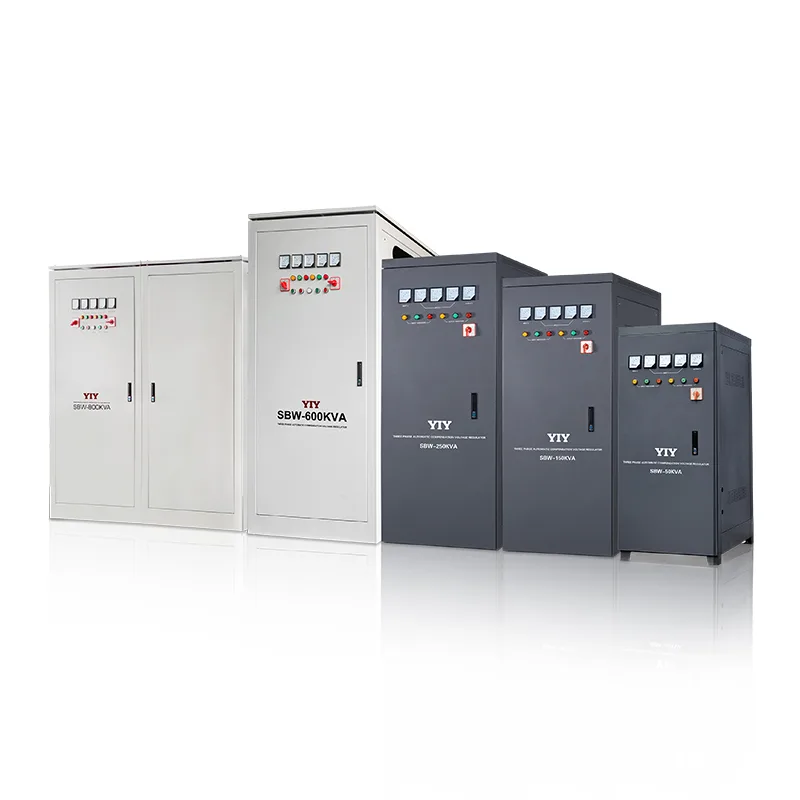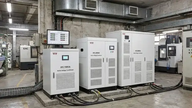
A three phase stabilizer regulates all three phases of an industrial supply at once, so motors, CNC machines, chillers, and VFD-driven pumps keep running through sags, swells, and phase imbalance. This guide covers when you need one, which topology fits, and how to size it.
Unpredictable grid voltage puts your heavy-duty motors at risk of premature failure and unplanned stoppages. Choosing the right three phase stabilizer dictates whether your production line runs efficiently or constantly fights regulation drift.
Why Does Single-Phase Regulation Fail Heavy Industrial Loads?
You will quickly discover why cascading single-phase regulators creates hidden bottlenecks when your plant scales beyond light commercial operations. If you are running CNC spindles, industrial HVAC chillers, or VFD-driven pumps on a bank of isolated single-phase units, you are likely trading short-term procurement savings for long-term maintenance tax.
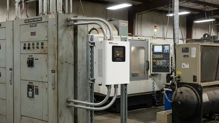
Chronic voltage sags and phase imbalance force your three-phase motors to compensate for missing phase current, which increases copper and core losses in the windings. Even modest phase-to-phase imbalance makes motors run hotter, and bearing lubrication breaks down faster under that thermal stress.
In practice, your drives draw extra current just to hold torque. That shortens spindle bearing life and lowers HVAC compressor efficiency, which is why dedicated three-phase regulation is worth it on motor-heavy feeders.
Wiring multiple single-phase regulators in parallel creates an uneven load-sharing bottleneck that standard panel designs rarely mitigate. One unit will consistently shoulder a higher percentage of the inrush current during heavy duty cycle startups, triggering nuisance trips while the others sit idle. This cascading fault forces you to constantly rebalance tap settings and replace fried contactors, turning routine voltage management into a recurring operational headache for you.
Move to a unified three-phase regulator when your logs show persistent phase imbalance or when motor loads make up most of the feeder. One unplanned spindle stoppage can cost more in lost throughput and expedited repair than the price gap between the two approaches.
A centralized unit also gives you consolidated power monitoring, phase-balance logging, and alarm outputs that can feed your SCADA or CMMS workflow.
Which Stabilizer Topology Best Matches Your Voltage Fluctuation Profile?
You will make smarter capital decisions when you compare your logged input variance against proven stabilization architectures before locking in a procurement order. Mapping your site’s daily voltage swing to the correct topology prevents you from leaving capital on the table while exposing critical machinery to avoidable thermal and electrical stress.
To help you evaluate the trade-offs quickly, review this architectural comparison:
Topology Correction Method Output Precision Response Time Best Suited For Your… Relay Electromagnetic tap-switching ±5% to ±8% ≤20 ms Non-critical lighting, HVAC compressors, budget constraints Servo Motor-driven carbon brush tracking ±0.5% to ±3% ≤1–2 seconds CNC spindles, packaging lines, moderate grid swings IGBT Solid-state double-conversion (AC/DC/AC) ±0.5% <1 ms (continuous) Mission-critical PLCs, medical imaging, severe harmonic noise
What these specifications mean for you is straightforward: a relay unit provides discrete, stepped correction that might cause minor flicker but is perfectly adequate for your auxiliary loads. A servo system gives you continuous, smooth adjustment that eliminates micro-trips during heavy duty cycles. An IGBT converter completely rebuilds your sine wave, meaning your most sensitive instrumentation never experiences upstream transients. You can see exactly how capacity sizing intersects with these technologies in our detailed guide on the 20kva voltage stabilizer.
Putting a relay unit on a process that actually needs servo precision creates a hidden maintenance cost: nuisance trips during motor starts and faster winding wear. Matching topology to load keeps capital spending tied to your real scrap and downtime risk.
Enclosure matters as much as topology. For dusty halls or outdoor bays, compare the SBW-F IP54 three-phase servo stabilizer with standard indoor cabinets; the sizing section below covers the site checks.
How Do Relay, Servo, and IGBT Stabilizer Circuits Work?
You need to understand exactly how each topology physically adjusts the voltage waveform in real time before you finalize your procurement specification. Mapping the correction mechanics directly to your load sensitivity gives you a defensible engineering rationale during internal approvals.
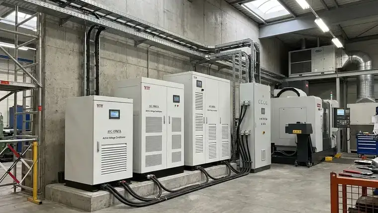
Relay stabilizers rely on an electromagnetic contactor array to instantly jump between autotransformer taps. When the control circuit detects a deviation, the coil fires to bridge a new winding segment, maintaining a ±5%–±8% output tolerance with a sub-cycle (≤20 ms) response. In practical terms, this means your lighting banks and non-critical HVAC units receive near-instant discrete correction without mechanical wear, though you will observe minor transient flicker during rapid grid swings.
Instead of stepping taps, the servo architecture uses a continuously rotating carbon brush riding along an exposed winding to fine-tune the transformation ratio. The analog tracking delivers ±0.5%–±3% precision with a ≤2-second correction window as the micro-step controller smoothly repositions the brush. For your daily operations, this continuous adjustment eliminates micro-trips that typically accompany relay systems, keeping your CNC controllers and packaging lines synchronized under heavy duty cycles.
IGBT units skip electromechanical correction entirely: they rectify incoming power into a DC bus, then rebuild the output waveform with high-speed pulse-width modulation. Because correction is electronic, upstream transients are largely kept away from downstream equipment. For cleanroom servers and precision PLC networks, that’s the main reason to pay for IGBT voltage stabilizers.
Cost-of-Inaction Note: A relay unit on a sensitive line may look cheaper upfront, but a single scrap event caused by stepped transients can outweigh that saving. Price the risk with your own scrap and downtime figures before you choose on unit cost.
How to Size and Select the Right Three Phase Stabilizer?
You must follow a repeatable workflow to translate your actual load profile into exact hardware specifications before finalizing your procurement order. This three-step checklist prevents you from installing an undersized cabinet that nuisance-trips during motor startups or wasting valuable floor space on oversized hardware.
Step 1: Load Calculation Protocol
Start by listing the running load of every machine that can operate at the same time. If you only know kW, convert it with kVA = kW ÷ power factor: a 20 kW load at 0.8 PF is 25 kVA.
Then add a starting-current margin for VFDs and large induction motors, and ask the supplier to check it against the unit’s overload rating. Plants with frequent heavy starts need more margin than steady process loads. For deeper capacity matching, see our 3 phase stabilizer sizing and comparison article.
Step 2: Environmental & Wiring Constraints
Check that the installation bay leaves the ventilation clearance the manufacturer specifies on every side. Heat trapped in a cramped bay derates the transformer, and you’ll notice it first during peak summer demand.
If the room is dusty, humid, coastal, or near washdown areas, specify the enclosure by its IP code under IEC 60529. An IP54 cabinet is dust-protected and resists splashing water, but you still need to confirm cooling, cable glands, and condensation control. Plan a manual bypass too, so operations can keep running during maintenance.
Step 3: Compliance Checkpoints & Operational Visibility
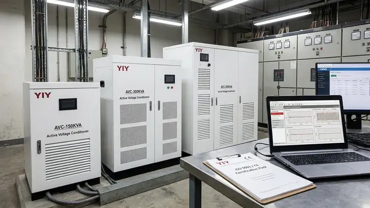
Align your specification with IEC 60038 standard voltages and request the supplier’s ISO 9001 and CE documentation before you sign. Confirm the output accuracy the quoted model holds at your lowest measured input, since that’s the band your PLCs and instrumentation will actually see.
Finally, check that the unit offers event logging and remote alarm outputs your SCADA or CMMS can read. Catching a phase imbalance early costs far less than a line stoppage.
Frequently Asked Questions
What Site Conditions Should You Verify Before Choosing a Three Phase Stabilizer?
Take L-L and L-N readings during normal production, peak startup, and low-grid periods. Then confirm floor space, cabinet door swing, cable entry direction, dust level, humidity, and condensation risk. If the room sits near furnaces, compressors, outdoor doors, or washdown zones, ask the supplier to mark ventilation clearance and gland positions on the approval drawing before production.
How Do You Build a Load Sheet for Sizing?
Split the sheet into continuous, intermittent, and starting loads. Record kW, kVA, power factor, operating sequence, and whether each motor starts direct-on-line, by soft starter, or by VFD ramp. Once you have simultaneous demand, have the supplier confirm that the continuous rating and overload curve cover it. If production may expand soon, include the future machine nameplates now so the cabinet isn’t undersized at commissioning.
Which Documents Should You Check Before Releasing the Purchase Order?
Ask for certificate copies, a routine test report template, the wiring diagram, a protection-device list, a nameplate sample, warranty terms, spare-parts availability, and the maintenance schedule. Then compare the quoted voltage, frequency, IP rating, and kVA across the datasheet, nameplate draft, and wiring diagram. Resolve any mismatch in writing before shipment inspection or factory acceptance.
Final Thoughts
Match topology to your logged grid variance, size for motor starting current, and confirm cooling limits before you buy. Then send your load list, input-voltage window, and motor starting data for a sizing review, or compare YIY three-phase stabilizers.