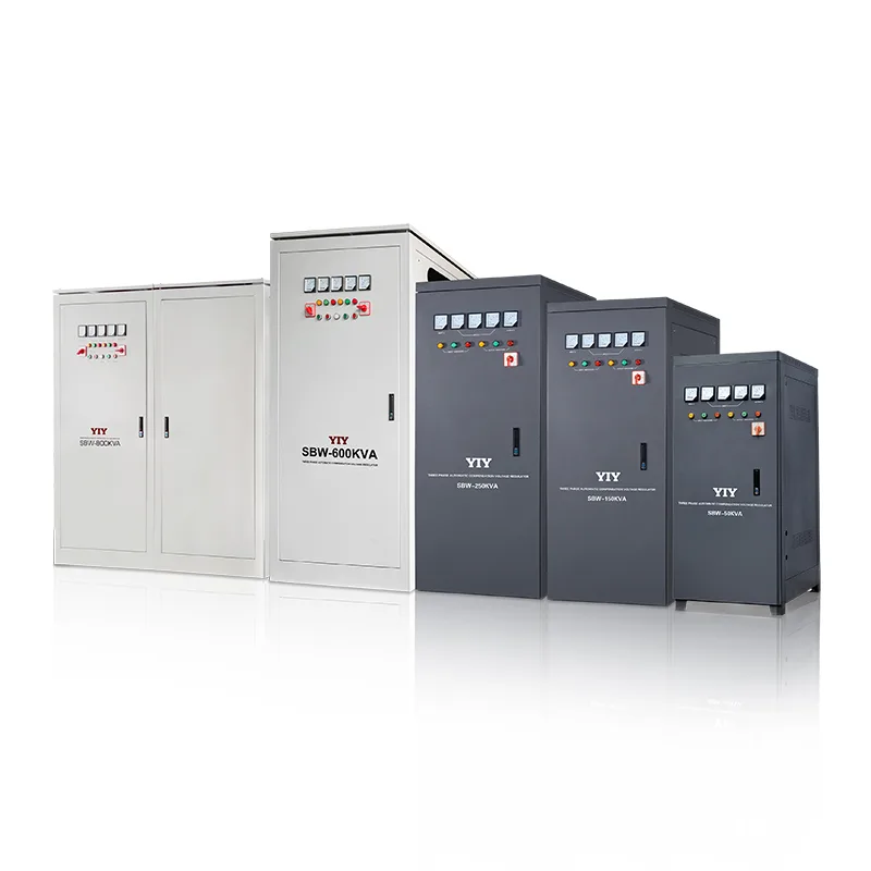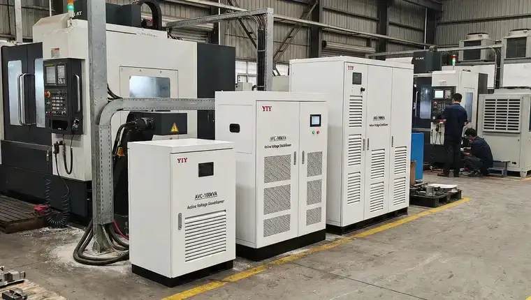
Voltage fluctuations from unstable utility grids can damage sensitive industrial equipment, trigger production downtime, and void manufacturer warranties. For facility managers and procurement teams evaluating protection options, understanding how voltage stabilizers work is essential to selecting the right technology for your load profile and operating environment.
Voltage stabilizers maintain constant output voltage despite input variations through three core technologies: relay-based tap switching, servo-driven autotransformers, and IGBT pulse-width modulation. Each approach offers distinct tradeoffs in precision, response time, and cost. This guide explains the operating principles behind relay, servo, and IGBT stabilizers, the standards that govern their performance, and the selection criteria that determine which type fits your application best.
What Voltage Stabilizers Do and Why They Matter
A voltage stabilizer is an electrical device that automatically maintains constant output voltage regardless of fluctuations in the input supply. When utility grid voltage sags below or surges above nominal levels—common in regions with unstable infrastructure or during peak demand periods—the stabilizer compensates through buck or boost operations to deliver steady power to connected equipment. This automatic regulation happens continuously, with response times ranging from milliseconds to seconds depending on the technology type.
Equipment Damage from Voltage Variations
Voltage fluctuations cause three primary failure modes in industrial equipment. Voltage sags (drops below nominal) force motors to draw excessive current to maintain torque, overheating windings and shortening insulation life. Voltage surges (spikes above nominal) stress semiconductor components in PLCs, drives, and control systems, leading to immediate failure or cumulative degradation. Sustained brownouts—prolonged low-voltage conditions—cause transformers and power supplies to overheat while starving downstream circuits, triggering nuisance shutdowns or data corruption in process controllers.
When Stabilization Becomes Critical
Voltage stabilization shifts from optional to mandatory when input variation exceeds equipment tolerance or when downtime costs outweigh protection investment. IEC 60038 standards assume utility voltage within ±10% of nominal, but many industrial sites experience ±15-20% swings during grid disturbances. CNC machines, medical imaging equipment, and data centers typically require input stability within ±3-5% to prevent positioning errors, image artifacts, or server crashes.
Facilities operating in emerging markets, remote locations, or areas with aging grid infrastructure face the highest risk and see the fastest ROI on stabilization.
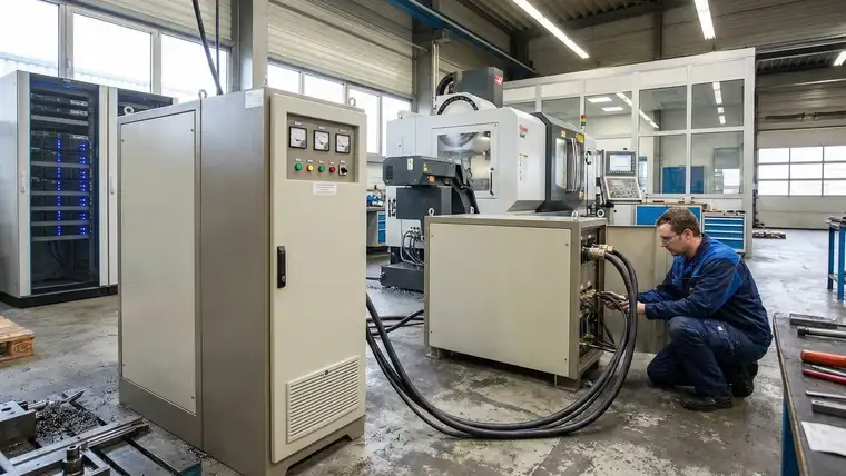
The decision to deploy stabilizers hinges on three factors: measured input voltage range at the site, equipment manufacturer voltage tolerance specifications, and the cost of a single unplanned shutdown. A 30-second voltage sag that trips a production line can cost more than a properly sized stabilizer, making protection a risk management decision rather than a technical preference.
Three Core Technologies: Relay, Servo, and IGBT
Voltage stabilizers achieve regulation through three distinct control mechanisms, each trading off precision, response speed, and cost. Understanding these operating principles helps match technology to load requirements and budget constraints.
Relay-Based Tap Switching
Relay stabilizers use electromagnetic contactors to switch between fixed transformer taps in response to input voltage changes detected by a control circuit. When input voltage drops below a threshold, relays engage to select a higher tap ratio, boosting output voltage in discrete steps—typically 2-4% increments. This stepped correction delivers ±5-8% output precision, sufficient for resistive loads like lighting and heating that tolerate moderate voltage variation. Response time ranges from 20-50 milliseconds per step, fast enough for most general-purpose applications.
The mechanical switching action produces audible clicks during tap changes and subjects relay contacts to wear over time, requiring periodic maintenance in high-cycling environments.
Servo-Driven Autotransformer
Servo stabilizers employ a motor-driven carbon brush that slides along the exposed winding of an autotransformer, continuously adjusting the turns ratio to match input fluctuations. A microcontroller monitors input and output voltage, commanding the servo motor to reposition the brush for precise correction. This continuous adjustment mechanism achieves ±0.5-3% output precision with typical response times of 1-2 seconds for full correction across the input range.
The carbon brush requires replacement every 2-3 years depending on duty cycle, but the servo approach eliminates the discrete steps and switching transients inherent to relay designs. Servo stabilizers dominate industrial applications where precision matters but sub-second response is acceptable.
IGBT Pulse-Width Modulation
IGBT stabilizers use insulated-gate bipolar transistor semiconductors controlled by a digital signal processor to regulate voltage through pulse-width modulation. The topology converts incoming AC to DC, then inverts back to AC at the desired voltage and frequency—a double-conversion architecture that provides complete galvanic isolation from grid disturbances. PWM switching at 10-20 kHz enables ±0.5% precision with response times under 10 milliseconds.
The solid-state design eliminates mechanical wear and switching noise, but the AC-DC-AC conversion introduces harmonic distortion that requires output filtering and increases system cost by 40-60% versus servo equivalents.
| Technology | Precision | Response Time | Mechanism | Best For |
|---|---|---|---|---|
| Relay | ±5-8% | 20-50ms | Tap switching | General loads, budget-sensitive |
| Servo | ±0.5-3% | 1-2s | Motor + brush | Industrial balance |
| IGBT | ±0.5% | <10ms | PWM conversion | Mission-critical precision |
Standards and Compliance Requirements
Voltage stabilizer selection and deployment must align with international standards that define performance thresholds, quality management, and electromagnetic compatibility. These requirements affect both product specification and vendor qualification during procurement.
IEC 60038 Input Variation Handling
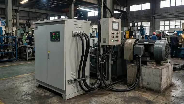
IEC 60038 establishes the global standard for voltage levels in low-voltage AC systems, specifying that equipment must handle input variations of ±10% from nominal voltage. Stabilizers designed to this standard accept input ranges like 160-260V for220V nominal systems or 190-260V for 230V systems, delivering regulated output within ±1-3% depending on technology type.
Sites experiencing voltage swings beyond ±10%—common in regions with aging grid infrastructure or high industrial load density—require stabilizers with extended input ranges, typically ±15-20%, to maintain protection without triggering bypass or shutdown modes.
ISO 9001:2015 Quality Management
ISO 9001:2015 certification indicates that a manufacturer maintains documented quality management systems covering design, production, testing, and service. For voltage stabilizers, this translates to traceability in component sourcing, calibrated test equipment for output precision verification, and corrective action procedures when units fail acceptance testing. Procurement teams evaluating suppliers should verify ISO 9001:2015 scope explicitly covers stabilizer manufacturing rather than general business operations, and request evidence of recent surveillance audits to confirm ongoing compliance rather than lapsed certification.
CE Marking and EMC Compliance
CE marking confirms conformity with European Union safety and electromagnetic compatibility directives, specifically the Low Voltage Directive (LVD) and EMC Directive. EMC compliance per IEC 61000 standards ensures stabilizers neither emit excessive electromagnetic interference that disrupts nearby equipment nor suffer susceptibility to external interference that degrades regulation performance. Industrial environments with variable frequency drives, welding equipment, or RF transmitters require stabilizers with demonstrated immunity to conducted and radiated disturbances, validated through third-party EMC testing rather than manufacturer self-declaration.
Choosing the Right Type for Your Application
Selecting the appropriate voltage stabilizer requires matching technology characteristics to four primary factors: connected load profile, output precision requirements, budget constraints, and operating environment. A systematic evaluation of these criteria prevents both over-specification—paying for precision you don’t need—and under-specification—risking equipment damage or production losses from inadequate regulation.
Load Type and Precision Requirements
Resistive loads like lighting, heating elements, and general-purpose motors tolerate wider voltage swings and operate reliably with relay stabilizers delivering ±5-8% precision. Inductive loads such as transformers and large motors benefit from servo stabilizers’ ±0.5-3% precision, which prevents the cumulative heating and efficiency losses that occur when voltage drifts outside narrow bands.
Sensitive electronic loads—CNC controllers, medical imaging systems, data center servers, and laboratory instruments—demand IGBT stabilizers with ±0.5% precision and sub-10ms response to prevent microprocessor resets, data corruption, or positioning errors during transient events.
Application Examples by Technology Type
CNC machining centers processing aerospace components require servo or IGBT stabilizers to maintain spindle speed accuracy and prevent tool path deviations that create scrap parts. General industrial facilities running conveyors, pumps, and HVAC systems achieve adequate protection with relay stabilizers at 40-60% lower capital cost than servo equivalents. Mission-critical applications—hospital operating rooms, semiconductor fabrication clean rooms, financial trading floors—justify IGBT investment through the cost avoidance of a single voltage-induced failure event.
YIY Product Range and Type Availability
YIY manufactures voltage stabilizers from 0.5KVA for small equipment protection through 3000KVA for facility-wide installations, with relay, servo, and IGBT technologies available across the capacity spectrum. Single-phase units serve residential and light commercial applications up to 30KVA, while three-phase configurations handle industrial loads from 10KVA to 3000KVA. Custom voltage ranges, input frequency options, and environmental enclosures extend the standard product line to specialized requirements including outdoor installations, high-altitude operation, and extreme temperature environments.
For buyers moving from technology theory into specification work, our servo stabilizer for CNC machines guide covers machining-cell protection in practice, while the 200 KVA servo stabilizer price guide explains when facility-scale projects cross into the 200 KVA pricing and configuration threshold.
Decision Framework
Choose relay stabilizers when input voltage varies ±10-15%, loads tolerate ±5-8% output variation, and initial cost drives the decision. Select servo stabilizers for industrial applications requiring ±1-3% precision with moderate response times and proven long-term reliability. Specify IGBT stabilizers only when loads demand ±0.5% precision, sub-second response to transients, or complete galvanic isolation from grid disturbances justifies the 40-60% cost premium over servo technology.
Sizing and Implementation Considerations
Proper stabilizer sizing requires matching capacity to total connected load, accounting for input voltage variation, and evaluating installation environment constraints. Under-sizing leads to overload trips and inadequate protection, while over-sizing wastes capital and increases operating costs through reduced efficiency at partial load. A systematic approach to capacity calculation, voltage range verification, and environmental assessment prevents both failure modes.
When the project uses a 240V industrial panel, apply the 240V conditioner RFQ checks to your measured voltage window and startup-load data before comparing supplier quotations.
Load Capacity Calculation
Calculate required stabilizer capacity by summing the nameplate ratings of all connected equipment, then applying a safety factor of 1.2-1.5× to account for inrush current and future expansion. Motors and transformers draw 3-7× rated current during startup, requiring either oversized stabilizers or soft-start devices to prevent nuisance trips. For mixed loads, separate resistive power (kW) from reactive power (kVAR) to determine total apparent power (kVA)—the stabilizer must handle the vector sum, not just the arithmetic total.
A 10kW motor with 0.8 power factor requires 12.5kVA stabilizer capacity, not 10kVA.
Input Voltage Range Matching
Verify that the stabilizer’s input voltage range encompasses the site’s measured variation with margin for worst-case conditions. A stabilizer rated for 160-260V input cannot regulate a site experiencing 150V sags without entering bypass mode, defeating the protection purpose. Measure input voltage over 24-48 hours including peak demand periods to capture transient events that instantaneous readings miss. Sites with ±15-20% variation require wide-range models, while ±10% sites can use standard-range units at lower cost.
Environmental and Installation Factors
Ambient temperature, altitude, and enclosure type directly affect stabilizer capacity and lifespan. Units derate 2-3% per 10°C above 40°C ambient, requiring oversizing or forced ventilation in hot environments. Altitudes above 1000m reduce cooling efficiency and dielectric strength, necessitating altitude-compensated designs or further derating. Outdoor installations demand IP54+ enclosures with corrosion-resistant coatings, while indoor units can use standard IP20 enclosures at lower cost.
Common Specification Errors
The most frequent sizing mistake is using equipment nameplate ratings without accounting for power factor, resulting in 20-30% undersizing for inductive loads. Specifying output precision tighter than load requirements wastes budget—general industrial equipment tolerates ±5% variation, making expensive ±1% IGBT stabilizers unnecessary. Ignoring input voltage range leads to bypass operation during the very sags the stabilizer should correct, a specification failure that only appears after installation when correction is expensive.
Frequently Asked Questions
What Precision Level Do I Need for My Equipment?
Start from the voltage tolerance printed in each machine’s manual and buy for the tightest one. Motors, pumps and HVAC usually accept a wide band, so a relay unit is often enough. CNC, imaging and process controls need tighter regulation, which points to servo. Loads that cannot ride through any disturbance call for an electronic IGBT design.
How Do I Calculate the Right Stabilizer Capacity?
Add up nameplate ratings in kVA, not kW, because inductive loads draw apparent power. Divide kW by power factor to convert. Then allow headroom for motor inrush, or fit soft starters so the stabilizer does not have to absorb it. Finally, compare a logged record of site voltage with the stabilizer’s rated input window.
What’s the Difference Between Relay and Servo Stabilizers?
A relay unit jumps between fixed transformer taps, so output moves in steps and the contacts wear with every switch. A servo unit moves a brush smoothly along the winding, so output tracks the setpoint more closely but corrects more slowly. Relay is the economical choice for tolerant loads; servo is the usual industrial choice when output stability matters.
Next Steps
Selecting the right voltage stabilizer requires matching three core factors to your application: technology type (relay for general loads, servo for industrial precision, IGBT for mission-critical equipment), capacity sized to total connected load plus safety margin, and input voltage range verified against your site’s measured fluctuations. Equipment tolerance specifications and operating environment constraints further narrow the selection.
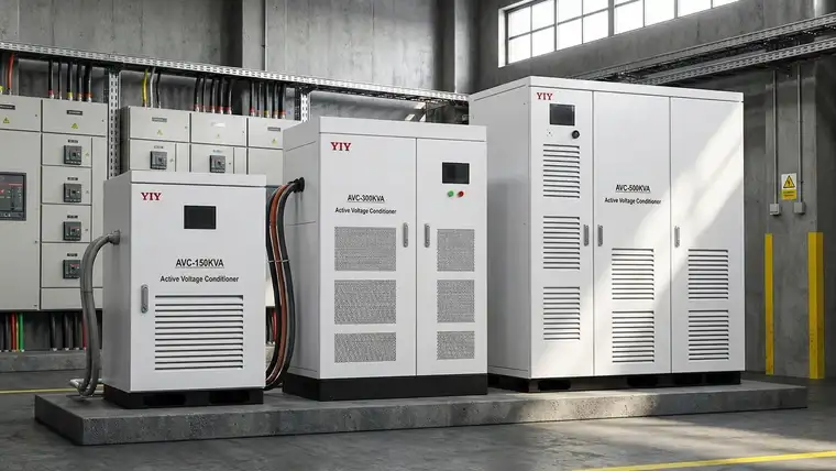
Before specifying a stabilizer, document your load profile—nameplate ratings, power factor, and startup current characteristics—along with site input voltage measurements over 24-48 hours. Share these details with YIY’s engineering team to receive a tailored recommendation that accounts for your specific voltage conditions, equipment protection requirements, and budget parameters. A properly matched stabilizer prevents both under-protection and unnecessary over-specification.
About YIY
Zhejiang Yiyen Holding Group Co., Ltd. (YIY) is a professional voltage stabilizer manufacturer with 16+ years of experience. With a 30,000sqm modern facility and an annual production capacity of 1,000,000+ units, our products are exported to 130+ countries. We provide OEM/ODM customization services and are ISO 9001:2015 certified, committed to delivering stable and reliable voltage protection solutions to global customers.
Contact Us
Email: yiyen@yiyen.com
Phone/WhatsApp: +86 13587452904
Website: https://www.yiyavr.com/
If you found this article helpful, contact us for a sizing review or customized solution.