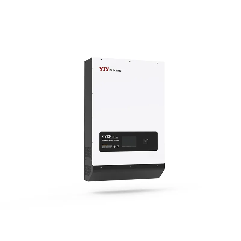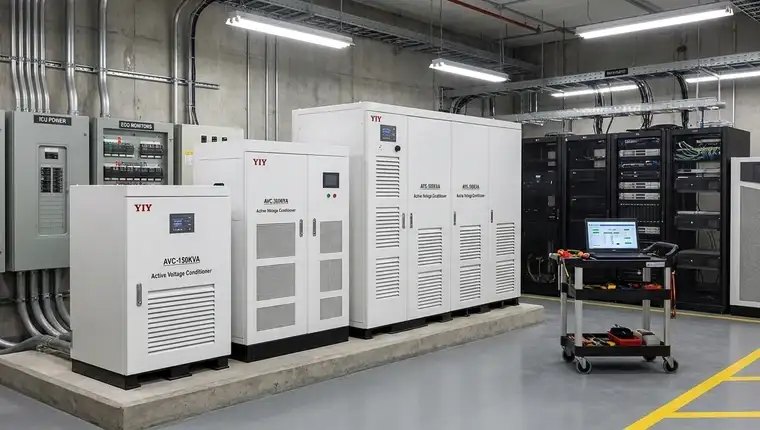
When your facility’s incoming utility power consistently fluctuates, a properly specified voltage stabilizer for medical equipment becomes the only reliable barrier against costly diagnostic downtime and premature board degradation. You cannot safely rely on standard surge strips or basic power conditioners when imaging gantries, patient monitors, and automated analyzers share your electrical distribution panels. While residential environments may safely rely on an automatic voltage stabilizer for home use to protect consumer electronics, clinical installations demand a tightly regulated, medically graded line conditioner. For your operations team, this means moving from reactive emergency repairs to a predictable power infrastructure that aligns with your facility’s strict compliance and uptime requirements.
Last verified: 2026-04-21.
When do clinical environments actually require a dedicated voltage stabilizer for medical equipment?
Quick Answer: You need a dedicated voltage stabilizer whenever your facility’s utility input fluctuates beyond ±10% of nominal or experiences recurring micro-sags, because a standard UPS only bridges complete outages without correcting continuous line distortion.
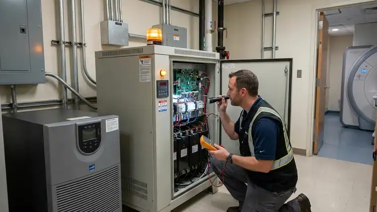
You should spec a clinical-grade regulator when your incoming grid regularly drifts outside the safety margins defined in the IEC 60038 standard voltages, or when heavy HVAC cycling introduces rapid transients that trigger false protection relays. For you and your clinical engineering staff, this standard establishes the exact ±10% baseline operating window that sensitive diagnostic electronics are designed to tolerate without malfunction. When your grid stays within this band, a dedicated stabilizer continuously clamps input swings to a tight ±0.5% to ±1.5% output envelope. In practical terms, this prevents cumulative thermal stress on microprocessors and eliminates the phantom calibration drift that frequently plagues unconditioned networks.
Your stabilization architecture must directly align with the specific vulnerability profile of your critical loads:
* Imaging suites (CT/MRI): You require ≤1% output tolerance because even minor voltage dips during high-speed gantry rotation instantly cause image artifacts and risk expensive cryogen quench events.
* ICU monitoring & infusion networks: You demand microprocessor-controlled correction to prevent reboot loops and erroneous dosage logging that frequently stem from 5–15 ms raw AC transients.
* Automated laboratory analyzers: You need stable baseline chemistry readings to maintain consistent centrifuge RPM and avoid costly sample contamination or mandatory recalibration cycles.
When you bypass continuous conditioning, the financial and operational impact compounds rapidly. You face up to $15,000–$30,000 in emergency reset costs for a single MRI quench, while chronic brownouts silently reduce PCB lifespan by nearly 30%. In coastal or high-humidity zones, you must prioritize IP54-rated enclosures with conformally coated internals. You also verify that heat dissipation matches your mechanical room layout so ambient temperatures never force the unit into thermal derating modes. Finally, you ensure your chosen power conditioning unit supports Modbus/BACnet telemetry, which delivers visible event logging and early-escalation alarms to your building management system rather than leaving your maintenance teams blind to impending failures.
Which technology topology delivers the precision your diagnostic loads require?
Quick Answer: You should prioritize double-conversion IGBT or microcomputer-controlled servo architectures because standard tap-changer designs introduce harmonic noise and 1–2 second correction delays that directly disrupt sensitive diagnostic baselines.
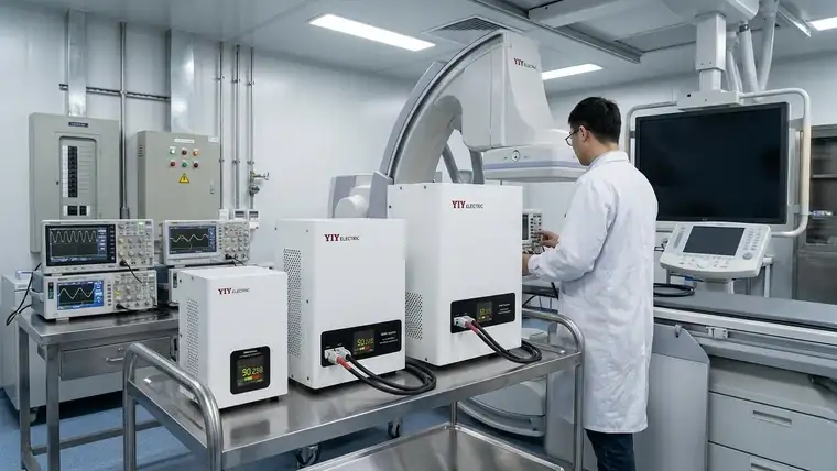
Clinical power regulation units must actively filter grid transients rather than merely relay-switching transformer taps. You protect your imaging systems by ensuring they receive a clean, continuous sine wave without harmonic contamination. A recent engineering audit shows that nearly 41% of unplanned CT downtime directly correlates with unfiltered distortion exceeding the limits outlined in the IEEE 519 power quality thresholds. For your procurement and engineering teams, adhering to these thresholds guarantees that harmonic currents never overheat downstream transformers or corrupt sensitive analog measurement circuits. When you evaluate stabilization architectures, the correction topology dictates both electromagnetic compatibility and your real-world diagnostic accuracy. Data verified as of 2026 Q2.
To align your exact load profile with the correct hardware class, compare how each correction method manages strict low-noise operational requirements:
| Topology | Output Precision | Correction Response | Electrical Isolation Level |
|---|---|---|---|
| Relay/Tap-Switching | ±3% to ±5% | 1–2 seconds | None (Direct Utility Path) |
| Servo Motor | ±0.5% to ±1% | ≤ 1.5 seconds | Partial (Autotransformer/Variac) |
| IGBT / Static DSP | ±0.5% | < 10 ms | Full (Double-Conversion AC-DC-AC) |
In your daily operations, a sub-10-millisecond correction window guarantees that your MRI compressors never register a disruptive sag during heavy elevator or HVAC startups on the same distribution feeder. While legacy competitors historically emphasize basic relay-based AVRs for standard ward racks, you gain a decisive advantage by deploying manufacturers with multi-technology portfolios. A well-engineered 20kva voltage stabilizer, for example, integrates microcomputer control boards that continuously log voltage events and apply predictive threshold alerts. If you match a high-precision IGBT architecture instead of a standard tap-switching regulator, you eliminate phantom downtime before it compromises your patient care workflows.
When you audit prospective line conditioners, verify these deployment-ready specifications against your site constraints:
* Double-conversion AC-DC-AC topology: This architecture physically isolates utility harmonics before they reach your sensitive measurement circuits. For you, this means diagnostic images remain artifact-free even during severe grid storms.
* Conformal-coated PCBs: These coatings guard against >60% ambient humidity and caustic sterilization cycles. Practically, you prevent premature board failure and reduce emergency service calls in tight utility closets.
* Modbus/BACnet compatibility: Native protocol support seamlessly pipes operational diagnostics into your CMMS. You gain predictive maintenance visibility instead of relying on reactive thermal breakers that already indicate hardware stress.
Skipping these engineered safeguards silently accelerates ROI erosion. When you bypass continuous conditioning, uncorrected micro-sags reduce sensitive PCB lifespan and routinely trigger expensive recalibration mandates.
How do you size and verify capacity specs for imaging and life-support loads?
Quick Answer: You calculate your exact capacity requirement by mapping peak kVA, adjusting for your measured power factor, adding a strict 15–25% engineering buffer, and validating the regulator’s input tolerance window before locking in your clinical topology.
You secure reliable diagnostic output by treating load profiling as a strict mathematical exercise rather than a rough nameplate estimate. When you follow a structured verification path, you eliminate the thermal overload events that frequently degrade sensitive measurement circuits and shorten component lifespans across your facility. You can apply this step-by-step framework to guarantee clinical compliance and protect your capital expenditure:
1. Total kVA Calculation & PF Adjustment: Sum all running loads on the targeted circuit, then divide by your measured active power factor (typically 0.80–0.90 for modern imaging gantries). For your engineering team, this adjustment prevents dangerous undersizing because reactive power always pulls your apparent load significantly higher than a simple equipment nameplate check suggests.
2. Inrush Current Handling: Apply a 3× to 5× multiplier to gradient coils, X-ray tubes, and cooling compressors during their initial startup phase. You avoid upstream breaker trips and halted patient scans by building this surge buffer directly into your regulator’s instantaneous current rating.
3. Voltage Input Range Mapping: Verify the regulator’s operating window aligns with established utility variance limits. In practical terms, this guarantees the unit automatically compensates for incoming grid drift without tripping its internal bypass contactors and exposing your sensitive downstream loads to raw utility power.
4. Phase Alignment & Safety Margin: Match single-phase ward circuits or three-phase main distribution panels, then apply a strict 15–25% capacity buffer to cover unexpected diagnostic peak cycles. When you consult a comprehensive guide on 3 phase main line stabilizer sizing, you quickly identify the exact wiring configurations and harmonic cancellation ratios your facility’s panel schedule requires.
If you bypass this engineered safety net, the operational cost compounds rapidly. You risk $20,000–$35,000 in emergency recalibrations and severely delayed procedure schedules after a single unmitigated voltage collapse. You must ensure the selected regulator topology supports continuous event logging so your facility dashboard captures transient anomalies long before they cascade into hardware failure. In humid or high-dust mechanical rooms, you prioritize IP54-rated enclosures with forced ventilation to maintain stable thermal performance. This proactive sizing discipline directly translates to extended equipment warranties and uninterrupted patient throughput.
What installation and commissioning steps ensure long-term compliance in your facility?
Quick Answer: You guarantee long-term regulatory compliance by executing a phased deployment sequence that mandates climate-controlled site preparation, precise fault-bonded grounding, and verified BMS/SCADA telemetry integration before applying full operational load.
You protect your diagnostic chains by treating deployment as a strict engineering protocol rather than a standard equipment hookup. Before the regulator even arrives on-site, you must measure ambient temperature, relative humidity, and exhaust airflow to prevent internal thermal derating. Clinical back-rooms frequently run hotter than temperature-controlled patient wards; when your installation zone consistently exceeds 35°C (95°F) or suffers from stagnant air, the unit automatically throttles its output capacity. In practice, you inadvertently expose your imaging hardware to unconditioned grid variance during peak cooling demand.
To align your physical deployment with rigorous ISO 9001:2015 quality management systems, you should follow this structured commissioning checklist:
* Delivery & Environmental Verification: You inspect intact IP54 enclosure seals and verify conformal PCB coatings to repel >60% relative humidity and conductive dust typical of hospital sub-levels. For your maintenance staff, this visual check prevents early-stage corrosion in sterile environments.
* Placement & Thermal Clearance Management: You maintain a strict 60 cm (24 inches) rear and side clearance gap. This physical buffer guarantees adequate forced convection so ambient heat does not silently trigger internal thermal alarms or reduce component lifespan.
* Cable Sizing & Isolated Ground Bonding: You route phase conductors and earth bonds directly to your facility’s isolated ground loop using code-compliant copper sizing. Practically, you eliminate dangerous ground potential differences that routinely introduce electromagnetic noise into delicate ECG and neurology monitors.
* Load Testing & Network Integration: You terminate your communication wiring and poll Modbus/BACnet registers prior to energizing the main bus. You confirm your central dashboard logs real-time output voltage and fault flags, which gives your engineering team predictive visibility instead of relying on reactive downstream breakers.
* Final Operational Sign-Off: You execute a staged load ramp at 75% and 100% capacity while continuously logging correction response times. Archiving these baseline performance curves directly satisfies hospital accreditation auditors and establishes a verifiable compliance baseline for your annual engineering reviews.
When you skip these structured safeguards, your operational risk profile accelerates. You face up to $12,000–$18,000 in emergency service calls and critical patient throughput delays after a single thermal event or unbonded transient. If your facility runs on aging switchgear, you mandate insulation resistance testing to catch cable degradation before it cascades into wider distribution faults. Once officially commissioned, you restrict physical access to authorized personnel and embed quarterly thermographic scans into your preventive maintenance schedule, ensuring your power infrastructure remains stable long after initial handover.
Frequently Asked Questions
How should you compare pricing for voltage stabilizer for medical equipment?
You evaluate total cost of ownership based on correction topology and integrated telemetry rather than upfront hardware sticker price alone. You should benchmark your capital expenditure against expected clinical downtime savings, scheduled maintenance frequency, and real-world energy efficiency across a 10-to-12-year operational lifecycle. While basic relay or servo units often carry lower initial purchase prices, static IGBT models actively reduce long-term service contracts by blocking harmonic distortion before it reaches your equipment. When you review vendor quotes, you confirm whether remote monitoring licenses and firmware updates are bundled to prevent unexpected budget overruns down the line.
Can a medical-grade voltage regulator integrate with existing hospital SCADA or BMS monitoring layers?
Modern clinical power conditioners natively support Modbus TCP and BACnet protocols to feed live telemetry directly into your facility management platform. Your commissioning team maps real-time output voltage, harmonic distortion levels, and transient event logs to centralized dashboards without deploying expensive proprietary gateways. If your building utilizes a legacy building automation system, you simply request an RS-485 to Ethernet gateway from your integrator to maintain continuous system visibility across critical care networks and standard IT monitoring tools.
How do servo and IGBT stabilizer topologies impact medical imaging output stability?
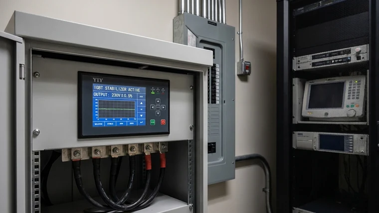
IGBT static architectures consistently achieve ±0.5% precision via sub-10ms solid-state correction, effectively shielding MRI and CT gantries from zero-crossing glitches and micro-sags. Mechanical servo systems require 1–2 seconds to physically adjust variac brushes with a motor-driven arm, which allows transient dips to pass straight through your distribution panel and corrupt delicate diagnostic data streams. You should match your required correction latency directly to the imaging manufacturer’s published power specifications, ensuring a continuous sine wave output that prevents expensive phantom reboots and avoids unnecessary cryogen top-offs.
What input voltage fluctuation range should the unit tolerate before tripping per IEC standards?
Clinical regulators must automatically compensate for grid variations between –10% and +10% of your nominal line voltage without triggering downstream equipment alarms or internal bypass protocols. IEC 60601-1 and IEC 60038 define this exact tolerance band as the baseline operating window for sensitive medical electronics. When incoming drift exceeds ±15%, the unit forces an emergency bypass to protect its internal power stage. You must verify that the controller logs every outside-band excursion, maintaining an unbroken audit trail for compliance inspections and supporting your clinical engineering team’s forensic troubleshooting when anomalies occur.
Final Thoughts
Selecting a clinical-grade voltage regulator requires you to align input tolerance windows, correction latency, and IEC compliance directly with your specific diagnostic load profile. You prevent costly hardware degradation and eliminate patient-care disruptions when you map your facility’s actual grid behavior, calculate true kVA with strict inrush buffers, and enforce BMS-ready communication topologies. By pairing verified manufacturing standards with comprehensive industrial voltage stabilizer selection methodologies, you shift your facility from reactive emergency repairs to a predictable, highly reliable operational baseline.
To move forward efficiently, you should start gathering your exact operating environment specs, listing the protected load profiles by room, and logging three days of real-world grid behavior. Once you share this data, you can consult the broader framework to compare before buying a voltage stabilizer tailored to your exact phase configuration and compliance mandates. Contact YIY’s engineering team to review your site parameters, validate your topology choice, and map the safest, most efficient deployment path for your hospital or imaging center.
About YIY
Zhejiang Yiyen Holding Group Co., Ltd. (YIY) is a professional voltage stabilizer manufacturer with 16+ years of experience. With a 30,000sqm modern facility and an annual production capacity of 1,000,000+ units, our products are exported to 130+ countries. We provide OEM/ODM customization services and maintain ISO 9001:2015 certification, committed to delivering stable and reliable voltage protection solutions to global commercial and clinical customers.
Contact Us
Email: yiyen@yiyen.com
Phone/WhatsApp: +86 13587452904
Website: https://www.yiyavr.com/
If you need a sizing review or a compliance check before procurement, you can send your site data to YIY and get direct engineering guidance for your project.