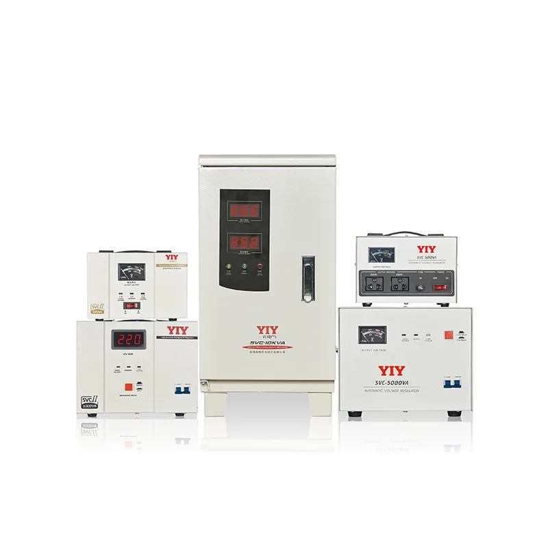
Use a single phase main line stabilizer when critical 120 V or 230 V loads sit on one feeder that keeps drifting outside utility tolerance and causes resets, nuisance trips, or weak starts. If the whole facility needs coordinated correction, look at three-phase instead.
This guide covers the risk of repeated sags, when a single-phase design beats three-phase, how relay, servo, and IGBT differ, and what to check before an RFQ. To rule out a plant-wide fix first, see the 3 phase main line stabilizer sizing guide.
What Operational Risks Appear When Single-Phase Input Voltage Drops Outside IEC Tolerance Bands?
If your branch feed keeps dropping outside the range your controls expect, the first damage usually appears in reliability rather than in dramatic failure. The IEC 60038 standard voltages define the nominal operating framework, but what matters on site is how often your real supply falls below that usable window during compressor starts, shift changes, or unstable utility periods.
On a lightly protected single-phase line, those repeated dips force control power supplies, inverter front ends, and small transformers to work harder than they were designed to.
For facilities teams, the early warning signs are usually easy to miss unless they are logged together:
- repeated PLC or controller restarts after short brownout events
- compressor or motor starts that sound sluggish even though upstream breakers remain closed
- recurring alarms that disappear after reboot and are misclassified as random faults
- cabinets that run hotter during unstable-grid days than during steady production days
The practical consequence is cumulative stress. Capacitors age faster, relays chatter, and timing-sensitive devices lose stability long before a catastrophic shutdown forces attention. If your site is dusty or poorly ventilated, the voltage issue also combines with heat and contamination, which is why enclosure protection and airflow matter almost as much as correction range.
How Prolonged Undervoltage Degrades Sensitive Loads
A prolonged undervoltage event rarely looks dramatic in the moment, but it steadily raises maintenance cost. Motors pull harder to produce the same torque, small control transformers run hotter, and boards that already live close to their design limit lose margin with every reset cycle.
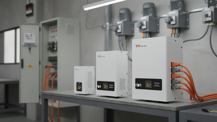
Three checks usually reveal whether the problem is already affecting production:
- Thermal behavior: Compare cabinet temperature on stable days and unstable-grid days to see whether line stress is adding avoidable heat to the enclosure.
- Reset frequency: Review controller, VFD, or UPS event logs rather than relying on operator memory; the pattern is often more consistent than the team assumes.
- Environment exposure: In high-dust or humid rooms, verify whether the enclosure and ventilation plan are protecting the electronics as well as the stabilizer itself.
For procurement teams, this is the point where a single-phase correction path becomes easier to justify. Even when the line is not failing outright, repeat resets, small batches of rejected output, and reactive service calls are usually enough to show that the feeder needs a more stable voltage environment.
When you are ready to shortlist hardware, the single-phase stabilizer models for 220/230V and 110/127V systems are listed with their published input ranges.
When Should You Deploy a Dedicated Capacity Tier Instead of a Three-Phase Topology?
Deploy a dedicated single-phase unit when the sensitive load group is concentrated on one feeder and does not justify a synchronized three-phase correction strategy. That is common in telecom rooms, medical support areas, isolated office or laboratory panels, and auxiliary production lines where the risk is local rather than facility-wide.
A dedicated single-phase tier usually makes sense when at least one of these conditions is true:
- the problematic loads are all on one 120V or 230V distribution path
- the site wants electrical isolation for a specialized room instead of balancing the whole bus
- neutral-current and feeder-quality concerns are localized, not plant-wide
- the budget supports targeted correction, but not a broader infrastructure project yet
For your shortlist, any one of these conditions is usually enough to justify a dedicated single-phase path before you expand the scope to a wider three-phase redesign.
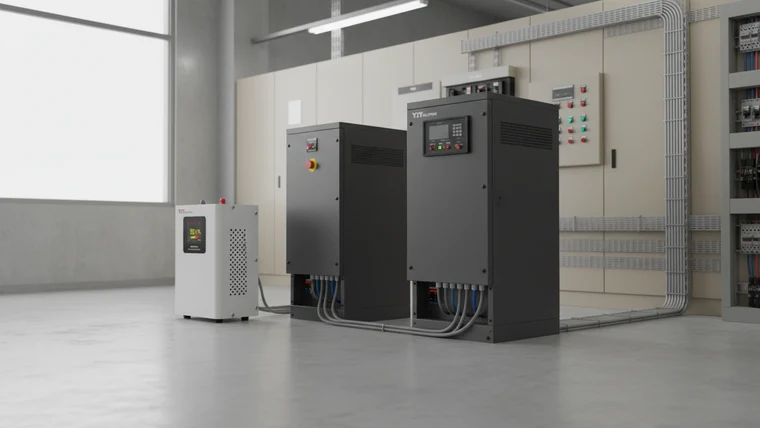
This is where topology decisions should become explicit. A three-phase design is still the better answer when the issue involves shared bus imbalance, multiple process lines, or a coordinated main distribution problem. But if the instability is limited to one feeder serving a narrow cluster of critical equipment, a dedicated single-phase unit reduces complexity, installation scope, and capital exposure.
Teams testing that boundary should use the industrial voltage stabilizer selection guide as the plant-wide cross-check before they commit to one direction.
When Unbalanced Loads Justify Dedicated Single-Phase Protection
Facilities with staggered HVAC compressors, mixed office or automation panels, or intermittent high-inrush devices often see a single feeder deteriorate long before the rest of the distribution system. In that situation, dedicated protection is not overdesign; it is fault containment.
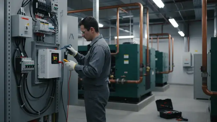
Telecom rooms and other specialized sites add one more reason: they often need an independent grounding path so ground loops don’t corrupt low-voltage signaling. A dedicated single-phase unit lets you plan that grounding and the regulator together for one room.
A focused single-phase design gives the team three practical advantages:
- Cleaner fault isolation: Engineers can separate feeder-specific instability from wider building-power issues.
- Lower project scope: Procurement can solve the immediate reliability problem without redesigning the entire distribution plan.
- Faster monitoring rollout: Event logging and alarm outputs can be tied directly to the affected panel, which makes trending and maintenance follow-up easier.
How Do Servo-Controlled and Relay-Based Designs Correct Main-Line Fluctuations in Real Time?
Match the correction method to the load tolerance first: relay designs correct in discrete steps, servo designs correct continuously, and IGBT designs respond fastest when electronics sensitivity is the dominant constraint.
The basic tradeoff is straightforward:
| Architecture | How it corrects | Best fit | Main tradeoff |
|---|---|---|---|
| Relay | Electromagnetic tap switching in discrete steps | Lighting, basic HVAC, general single-phase commercial loads | Lower cost and fast reaction, but less smooth output correction |
| Servo | Motor-driven continuous correction across transformer windings | Inverter equipment, control panels, mixed light-industrial loads | Better output stability, but more mechanical components to inspect |
| IGBT | Electronic high-speed conversion and correction | Sensitive electronics, instrumentation, and tighter tolerance applications | Highest performance, usually at higher cost and system complexity |
For your application review, use the table to eliminate one architecture first, then compare only the remaining candidates against startup behavior, maintenance constraints, and tolerance requirements.
Electromagnetic Relay Tap-Switching Principles
Relay-based correction remains a practical choice when the load can tolerate stepped regulation and the priority is dependable performance at reasonable cost. That is why the relay voltage stabilizer overview remains relevant for commercial and residential panels that do not need ultra-tight smoothing.
Servo Motor-Driven Autotransformer Mechanics
Servo-based designs are a better fit when the feeder serves inverter equipment or automation controls that respond badly to abrupt correction steps. In real terms, the value is not just better regulation; it is steadier restarts, fewer nuisance alarms, and better protection for devices that care about waveform continuity.
IGBT and Digital Stabilization Precision
IGBT designs belong in the discussion when the site needs faster correction and tighter control than either relay or servo can deliver. In practice, they are justified when the operational cost of instability is higher than the additional system cost. That is why procurement teams should compare them against actual fault tolerance and logging requirements, not just against brochure claims about precision.
Which Sizing Rules and Compliance Checks Ensure Your Equipment Matches the Actual Load Profile?
Start sizing from measured load behavior, startup current, ambient conditions, and documented installation assumptions. The goal is to buy the unit that fits the feeder, not the unit that looks safest on paper.
Use this procurement checklist before approving a model:
| Check | Why it matters | If you skip it |
|---|---|---|
| Continuous load and startup current | Confirms whether the unit can ride through normal operating demand and real inrush events without nuisance tripping | The stabilizer may appear large enough at steady state but still fail during starts or transfer events |
| Input fluctuation range | Matches the selected correction window to the real site voltage log, not the salesperson’s assumption | The unit may spend too much time at its edge conditions and provide less usable protection than expected |
| Ambient temperature and enclosure rating | Verifies whether dust, humidity, and room heat will derate the unit or shorten component life | A technically correct unit can still become a maintenance problem if the enclosure and airflow assumptions are wrong |
| Application note and approvals | Ensures the selected model is actually intended for the feeder type and operating environment | Procurement may approve a model that carries the right headline rating but the wrong field application |
| Output accuracy requirement | Shows whether PLCs, HMIs, or medical devices will tolerate the corrected voltage | You can still get intermittent alarm faults after paying for a regulator |
| Bypass and protection logic | Confirms manual bypass, short-circuit protection, and surge suppression are included | One internal fault can stop the whole cell until a service call |
Which Documents Should Procurement Verify Before Approval?
Procurement should ask for four items before sign-off:
- the product data sheet with model-specific electrical range
- the application note or configuration guidance for the target load type
- factory test evidence tied to the offered model, not a generic catalog family
- current certification or quality-system documentation such as ISO 9001:2015
For your RFQ pack, keep those four items together with the feeder voltage log so engineering and procurement are reviewing the same evidence set before approval.
The most important action is cross-checking the model’s data-plate rating against the application note and the actual feeder configuration. That step catches a large share of preventable selection mistakes before the unit ever reaches site.
Frequently Asked Questions
What Is the Difference Between a Single-Phase Main Line Stabilizer and a Plug-In Appliance Stabilizer?
A main line stabilizer is designed to protect a feeder or panel, not just one outlet-level appliance. You use it when the problem is embedded in the incoming branch supply and multiple downstream devices need coordinated protection.
When Is a Three-Phase Main Line Design the Better Choice?
A three-phase main line design is the better choice when the instability affects a shared distribution bus, multiple process lines, or a coordinated industrial load set. If the issue is isolated to one feeder, a single-phase design is usually the more targeted answer.
Which Documents Should a Buyer Request Before Approving a Model?
A buyer should request the model data sheet, the application note, any model-specific test evidence, and current certification documents. Before approval, cross-reference the data-plate rating with the feeder type and the intended operating conditions.
What Should Maintenance Teams Log During Commissioning?
Maintenance teams should log feeder voltage behavior, startup current events, alarm history, and enclosure temperature during early operation. That record makes it much easier to distinguish site instability from equipment configuration mistakes later.
Final Thoughts
A single phase main line stabilizer is the right choice when one feeder repeatedly moves outside acceptable voltage range and the risk is concentrated on a defined load group. The technical decision should rest on measured voltage behavior, startup demand, environmental conditions, and equipment sensitivity rather than on catalog language alone.
Still screening suppliers? Start with the industrial voltage stabilizer manufacturers guide. With a short model list, use the compare before buying a voltage stabilizer checklist.
Then send feeder voltage range, startup current, enclosure conditions, and load type to yiyen@yiyen.com and we’ll recommend a configuration.
For this application, the TSS Wall-Mounted Voltage Stabilizer is a matched product option worth evaluating.