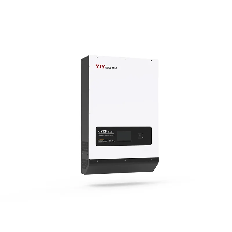

This IGBT Voltage Stabilizer application guide is for you when sensitive, mission-critical loads need faster correction, tighter output accuracy, and stronger disturbance control than a conventional servo or relay stabilizer can provide.
If your site runs semiconductor tools, medical systems, data center infrastructure, lab instruments, CNC controls, or generator-backed production equipment, a static AVR or digital voltage stabilizer becomes worth evaluating when voltage dips, swells, and fast fluctuations are already affecting uptime or measurement stability.
In this guide, you’ll compare when IGBT technology fits, how it differs from servo and relay designs, which sizing checks matter, what standards and documents to verify, and how to move from first-pass evaluation to procurement review.
When Is an IGBT Static Stabilizer the Right Fit?
You should choose an IGBT static stabilizer when your protected load cannot tolerate slow correction, broad voltage deviation, contact wear, or repeated reset events from fast grid disturbances.
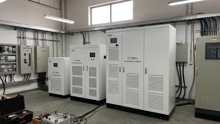
For you, the practical signal is not simply “the voltage is unstable.” The signal is that instability is interrupting a process, corrupting a test, triggering PLC alarms, delaying diagnostics, or creating maintenance events that your current AVR cannot explain. In those cases, a high-precision igbt voltage stabilizer should be evaluated as a performance-grade topology, not just another automatic voltage regulator option.
IGBT-based units use insulated-gate bipolar transistors as the electronic switching stage, typically controlled by DSP/PWM logic. In documented YIY IGBT designs, the technology can support ±0.5% output precision and correction in under 10 ms using DSP/PWM double-conversion architecture. For your equipment, that means the stabilizer is designed to keep voltage inside a much narrower window and recover fast enough to reduce nuisance trips during sudden dips or swells.
This fit is strongest when you see one or more of these conditions:
- Your load is sensitive to short voltage dips, not just long-term under-voltage.
- Your equipment requires tight output tolerance for calibration, recipe stability, or diagnostic accuracy.
- Your site has generator-backed supply with unstable voltage or frequency behavior.
- Your existing servo stabilizer corrects slowly during fast fluctuations.
- Your relay AVR creates step changes or contact-wear concerns under frequent switching.
- Your maintenance team needs alarms, metering, and event visibility instead of post-trip guessing.
For nominal voltage assumptions, you can align the project with IEC 60038 standard voltages. In practical terms, that standard helps you avoid designing around a vague “normal voltage” and instead specify the real nominal system voltage your stabilizer must support.
When Do Servo and Relay Stabilizers Become the Wrong Fit?
You are probably beyond a basic servo or relay AVR when your load trips faster than mechanical or step-based correction can respond.

A relay stabilizer changes taps in steps through contacts. That can be acceptable for simple, small, or less sensitive loads, but your critical equipment may still see abrupt voltage transitions. Frequent dips and swells can also increase contact wear, which matters when your load depends on consistent daily operation.
A servo stabilizer uses motor-driven correction through transformer or variac control. It can be a strong industrial choice where voltage drift is slower and precision requirements are moderate. The weakness appears when your feeder has rapid dips, repeated swells, heavy cycling, dust, heat, vibration, or a process that trips before the motorized correction finishes.
| Stabilizer type | Typical behavior | Where it struggles | What it means for you |
|---|---|---|---|
| Relay AVR | Step-based tap switching with mechanical contacts | Frequent dips, swells, contact wear, output step changes | Your equipment may see abrupt transitions and more maintenance events. |
| Servo stabilizer | Motor-driven correction through transformer/variac control | Fast disturbances, high cycling, dust, vibration, slow recovery | Your load may trip before correction is complete. |
| Static / digital stabilizer | Electronic correction using semiconductor switching and digital control | Requires careful sizing, thermal design, and specification review | You gain faster correction and tighter stability, but your site checks matter more. |
| IGBT double-conversion stabilizer | AC→DC→AC conversion with DSP/PWM inverter control | Higher technical and cost class than basic AVR designs | You get stronger disturbance separation for critical loads when the application justifies it. |
If your application is residential, light commercial, or small non-critical load protection, a relay voltage stabilizer may still be a practical and cost-conscious option. For your decision, the key is not whether relay technology is “good” or “bad”; it is whether step correction and contact-based switching are acceptable for your protected load.
Short voltage events deserve special attention. IEC 61000-4-11 voltage dips and interruptions immunity testing exists because brief dips and interruptions can disrupt electronic equipment even when average voltage readings look acceptable. For you, a sag that lasts only a few milliseconds can still reset a controller, stop a diagnostic scan, or interrupt a production recipe.
Which Applications Justify a Static AVR or Digital Voltage Stabilizer?
You should prioritize static AVR evaluation when the cost of a voltage event is operational disruption, not just equipment inconvenience.
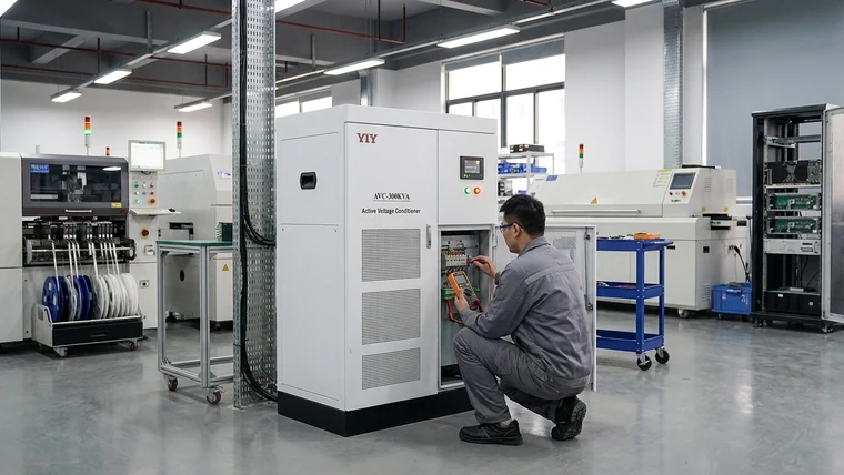
Typical high-fit environments include semiconductor manufacturing, SMT production, research laboratories, hospital equipment rooms, data centers, precision CNC systems, test benches, printing lines, metrology rooms, and generator-backed industrial sites. Your common thread is load sensitivity: if voltage deviation affects measurement, control logic, stored data, imaging quality, or production continuity, tighter correction becomes easier to justify.
For medical and laboratory environments, your review should focus on output stability, electrical isolation, alarm visibility, and documented protection functions. A generic capacity match is not enough if the load requires predictable output under fast grid changes.
For data centers and IT infrastructure, your stabilizer may sit upstream of UPS systems, cooling equipment, or distribution panels. In that case, confirm harmonics, bypass arrangement, grounding, and coordination with existing protection devices. Your goal is to improve power quality without creating a new compatibility issue.
For generator-backed sites, voltage regulation alone may not solve the full problem. If frequency also shifts under changing load, you may need a CVCF-style solution that stabilizes voltage and frequency together. In practical terms, that means your specification should include generator behavior under load steps, not only utility input voltage range.
For CNC and precision manufacturing, your load may include drives, controllers, motors, transformers, and auxiliary systems. Some parts of the line may tolerate slower correction, while control cabinets or test equipment may not. You can often get a better project result by separating critical and non-critical loads instead of applying the highest-cost topology to every panel.
What Technical Specifications Should You Verify Before Selection?
You should verify topology, response time, output accuracy, voltage range, overload capacity, IGBT limits, thermal design, harmonic behavior, bypass design, and protection functions before treating any static AVR as suitable for critical loads.
The most important question is whether the unit is truly designed for your disturbance profile. “IGBT” alone is not a complete specification. Your supplier should be able to explain how the stabilizer senses voltage, how the control loop responds, where the bypass is located, how the inverter is protected, and under what conditions accuracy and response-time claims were tested.
A double-conversion AC→DC→AC design first rectifies unstable input power and then reconstructs regulated AC output through an inverter stage. For you, that means the protected load is less directly exposed to incoming grid disturbance than it would be with a simple line-interactive correction design.
When a supplier states ±0.5% output accuracy, ask whether that value applies across the full input voltage range, at different load levels, and during load steps. In practical terms, an accuracy number is only useful if your equipment sees that stability during real operating conditions, not only during a laboratory demonstration.
When a supplier states <10 ms correction, ask what dip depth, input condition, and load percentage were used for the test. For your site, the difference between a marketing response number and a tested disturbance condition can determine whether controllers stay online or trip.
| Parameter | Why it matters | What you should verify |
|---|---|---|
| Topology | Confirms whether the unit is true static conversion or a simpler correction design | Ask whether it uses AC→DC→AC double conversion and where bypass is located. |
| Response time | Determines whether short dips become load interruptions | Request test conditions behind any <10 ms claim. |
| Output accuracy | Protects calibration, recipes, and control stability | Confirm whether ±0.5% applies across input range and load variation. |
| Input voltage range | Defines whether the unit can survive your worst feeder condition | Compare datasheet range against measured low/high site voltage. |
| IGBT voltage ratings | Prevents overstress during surges, switching, and overload events | Review device voltage rating, current rating, and thermal margin. |
| IGBT gate voltage | Affects safe switching control | Confirm gate-drive protection and limits against the inverter design. |
| IGBT saturation voltage / voltage drop | Influences heat and efficiency | Check cooling design, cabinet ventilation, and derating at ambient temperature. |
| Harmonics | Avoids solving voltage problems while creating distortion problems | Ask for THD data and filtering provisions. |
| Protection functions | Reduces fault escalation | Confirm overload, short-circuit, overtemperature, surge, phase loss, bypass, and alarm functions. |
| Monitoring | Supports maintenance and root-cause analysis | Look for metering, event logs, dry contacts, RS485, PLC/BMS/SCADA options where needed. |
If your site includes drives, UPS systems, rectifiers, or generator-backed feeders, use the IEEE 519 recommended practice for harmonic control as a reference point during harmonic discussions. For you, this means the stabilizer review should include distortion and filtering, not only voltage correction.
How Should You Size and Select the Right Unit?
You should size the stabilizer from measured load behavior and site voltage data, not from nominal kVA alone.
Start with your real operating demand. Confirm total connected load, normal running kW/kVA, power factor, inrush current, simultaneity, future expansion, and required safety margin. If you are protecting a three-phase main line, use a structured 3 phase main line stabilizer sizing process so your phase system, wiring, load balance, and protection assumptions are checked together.
The core sizing relationship is:
kVA = kW ÷ power factor
If your protected load is 80 kW at 0.8 power factor, the apparent power is 100 kVA. For you, that means a stabilizer selected only from kW could be undersized before inrush, overload, or margin is even considered.
Your selection checklist should look like this:
| Check | Why it matters | If you skip it |
|---|---|---|
| Total running kW/kVA | Sets the base capacity | You may undersize the stabilizer or buy unnecessary headroom. |
| Power factor | Converts real power into apparent power | Your selected kVA may not match actual current demand. |
| Startup / inrush current | Motors, transformers, compressors, and drives can draw high starting current | The unit may trip during startup even if running load looks acceptable. |
| Simultaneity | Not every load starts or runs at once | You may over-spec the whole project. |
| Single-phase vs three-phase | Defines topology, wiring, balancing, and protection | You may select the wrong electrical architecture. |
| Measured low/high input voltage | Confirms required correction range | The unit may fail during the site’s worst condition. |
| Fluctuation speed | Separates servo-suitable drift from static-AVR events | Your equipment may trip before correction completes. |
| Ambient heat and ventilation | Affects IGBT and transformer thermal margin | Component life and reliability may fall. |
| Dust, humidity, altitude, enclosure | Determines cabinet and cooling requirements | The stabilizer may degrade in the real installation environment. |
| Monitoring and alarms | Helps your maintenance team diagnose events | You lose evidence after nuisance trips. |
For a broader project framework, align your review with industrial voltage stabilizer selection criteria before you request final quotations. That helps you compare load profile, input range, application sensitivity, environment, serviceability, and documentation instead of comparing only price and kVA.
What Documents Should You Request Before Procurement Approval?
You should request model-specific documents that prove the stabilizer you are buying matches the quotation, datasheet, installation environment, and protected load.
A static AVR or digital voltage stabilizer is often purchased for a critical process, so your procurement screen should be stricter than a basic catalog comparison. If the document set is incomplete, your approval risk increases even when the headline specifications look attractive.
| Check | Why it matters | If you skip it |
|---|---|---|
| Datasheet with exact model number | Confirms capacity, voltage range, accuracy, and topology | You may approve a different configuration than the one specified. |
| User manual | Shows installation, operation, alarms, and maintenance requirements | Your installer may miss wiring, clearance, or safety requirements. |
| Wiring diagram | Confirms input/output, bypass, grounding, and control connections | Site wiring errors can delay commissioning. |
| Test report | Supports response time, accuracy, overload, and protection claims | You rely on unverified marketing numbers. |
| Protection list | Confirms fault handling and alarms | Critical faults may not be covered. |
| Harmonic data | Matters for UPS, drives, rectifiers, and generators | You may create a new power-quality issue. |
| Enclosure and cooling details | Matches cabinet to heat, dust, humidity, and ventilation | Thermal problems may appear after installation. |
| Warranty and service terms | Defines support after commissioning | Your downtime response may be unclear. |
| Certification files where required | Supports import, compliance, and project approval | Procurement or inspection may be delayed. |
For semiconductor-level review, be practical. You do not need to redesign the inverter, but you should ask how IGBT voltage ratings, gate voltage limits, saturation voltage, switching loss, and thermal protection are managed. If a supplier references a module brand, verify the exact module part number and revision against that manufacturer’s official technical documentation.
How Should You Compare Cost Without over- or Under-Specifying?
You should compare cost against risk, disturbance speed, protected-load sensitivity, and documentation quality—not just against the lowest kVA price.
An over-specified project ties up capital in performance your load may never use. An under-specified project converts voltage instability into downtime, rejected batches, delayed diagnostics, failed calibration, or emergency service. Your best procurement question is not “Which stabilizer is cheapest?” but “Which topology and capacity tier protects the electrical behavior that actually threatens this process?”
For critical loads, your comparison should separate three cost layers:
- Equipment cost: stabilizer capacity, topology, cabinet, monitoring, bypass, and protection options.
- Integration cost: wiring, ventilation, floor space, shutdown window, upstream/downstream coordination, and commissioning.
- Operational risk: nuisance trips, lost production, data loss, maintenance time, and service response.
If you are evaluating a defined capacity class, it can help to compare before buying a voltage stabilizer so your team reviews specification, sourcing, and acceptance checks before issuing a purchase order.
Frequently Asked Questions
Is an IGBT Voltage Stabilizer Application Guide PDF Free Download Enough for Technical Selection?
A free PDF is only a starting reference. You should verify the latest supplier datasheet, model-specific manual, wiring diagram, rated input range, output accuracy, response-time test conditions, bypass design, protection list, and certification files before using it for procurement approval. If the PDF came from a third-party upload site, check the revision number against the manufacturer’s official documentation.
When Should You Choose a Static AVR Instead of a Servo Voltage Stabilizer?
You should choose a static AVR when your protected load needs faster correction and tighter voltage regulation than a servo stabilizer can provide. Before specifying one, measure your low/high input voltage, fluctuation speed, load kVA, power factor, startup current, ambient temperature, and required output tolerance, then compare those values with the supplier’s tested conditions.
Where Should You Verify the Official Manual for Fuji IGBT Modules?
You should verify the official manual for Fuji IGBT modules on Fuji Electric’s own technical documentation or regional support website. Use the exact module part number, package type, voltage rating, current rating, and revision date, then compare gate voltage limits, switching loss data, isolation rating, and thermal resistance against your stabilizer supplier’s inverter-stage design notes.
What Documents Should Procurement Request Before Approving a Digital or Static Stabilizer?
Procurement should request the datasheet, user manual, test report, wiring diagram, protection list, warranty terms, applicable certification files, input/output voltage range, rated kVA, overload capacity, enclosure rating, harmonic data where relevant, and local service support terms. As a concrete verification action, match the model number across the quotation, nameplate, manual, and test report before approval.
What Should You Do Next?
You should start with a quick fit review before asking for a fully engineered quotation.
Share your operating environment, protected loads, phase system, measured voltage range, disturbance symptoms, generator use, ambient conditions, and any trip history you already have. With that first-pass information, YIY can help you decide whether a servo stabilizer, relay AVR, static AVR, or IGBT-based digital stabilizer is the right deployment path for your site.