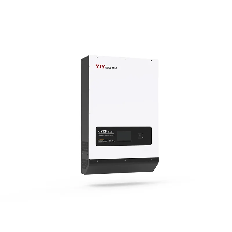
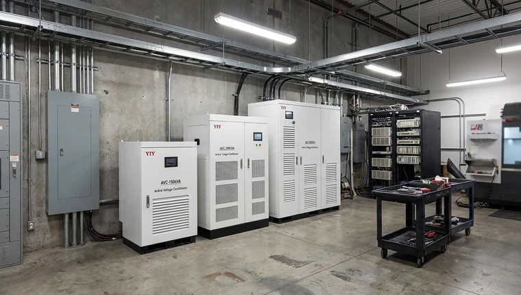
An igbt based voltage stabilizer is the right fit when your CNC machines, medical systems, telecom racks, automation panels, or other critical loads need fast static correction, grid isolation, and tight output regulation around ±0.5% that relay or many servo designs may not reliably maintain under unstable supply conditions.
If your load can tolerate moderate voltage variation, you may not need this premium topology. If one voltage dip can stop production, corrupt test data, affect imaging quality, or trigger repeated drive and PLC faults, you should evaluate IGBT/PWM stabilization as a risk-control decision rather than a simple AVR purchase.
This guide will help you decide when this topology fits, how it compares with relay and servo stabilizers, how to size it from real load data, which standards and documents to verify, and what to check before approving a supplier quotation.
When Does an IGBT Based Voltage Stabilizer Make Sense for Your Load?
You should consider this topology when voltage instability creates downtime, quality, safety, or compliance risk for your operation. The key question is not only whether your mains voltage fluctuates, but what happens to your protected equipment when that fluctuation reaches the load.
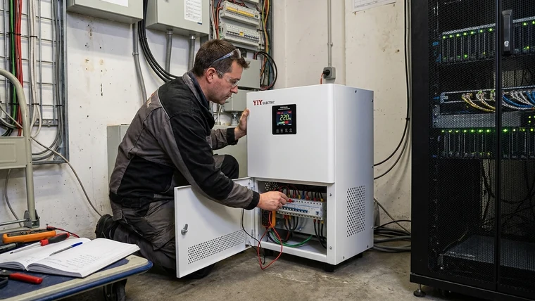
A basic stabilizer may be acceptable for lighting, general HVAC, or low-risk utility loads. Critical electronics behave differently. CNC controls, medical imaging systems, semiconductor equipment, telecom racks, robotic lines, PLC-controlled production, test benches, and SMPS-heavy panels often need tighter control because their electronics can trip, drift, or produce poor output quality during voltage events.
Typical fit conditions include:
- Your process cannot tolerate nuisance trips: CNC machines, robotics, packaging lines, and PLC systems lose production continuity when power quality events trigger faults.
- Your output quality depends on stable power: Medical imaging, laboratory equipment, printing, coating, electronics production, and calibration-sensitive processes can show quality deviation.
- Your load is electrically difficult: VFDs, rectifiers, UPS inputs, SMPS loads, and mixed control panels can introduce harmonics and non-linear current behavior.
- Your grid is unstable or harsh: Frequent sags, swells, weak feeders, generator operation, phase unbalance, or high ambient heat can make simple correction unreliable.
- Your downtime cost is high: When one shutdown affects production schedules, service contracts, or customer commitments, tighter voltage regulation can be justified.
For a product-level view of how this technology is packaged, ratings are arranged, and applications are positioned, you can review YIY’s igbt voltage stabilizer overview early in your evaluation.
In practical terms, an IGBT static voltage stabilizer is not “better for every load.” It is better for loads where the consequences of poor voltage control are expensive, disruptive, or hard to diagnose after the event.
How Is an IGBT Static Voltage Stabilizer Different from Relay or Servo Designs?
You get the main advantage from semiconductor-based correction: an IGBT static unit regulates electronically instead of relying on relay tap switching or motor-driven movement. That difference affects response behavior, precision, maintenance exposure, and application fit.
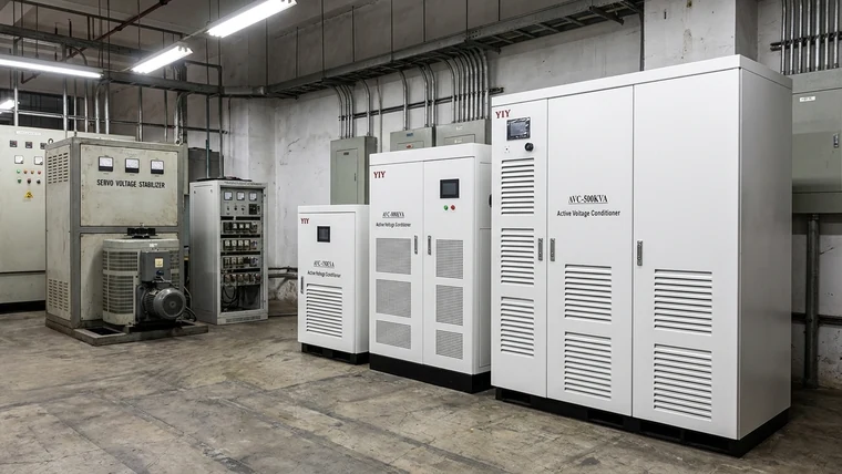
Relay stabilizers are usually the lowest-cost option. They correct voltage by switching transformer taps, which means the output changes in steps. This can be acceptable for tolerant loads, but the relay contacts are mechanical wear points and the regulation band is relatively wide.
Servo stabilizers use a motorized correction mechanism to adjust voltage more smoothly. A servo voltage stabilizer can be a strong choice for many industrial loads where precision is important but ultra-fast static correction is not mandatory. However, because servo systems include moving correction parts, you should account for motor, brush/contact, calibration, and service requirements.
IGBT static units use insulated-gate bipolar transistors, DSP control, and PWM switching. For your critical load, this means correction happens through electronic switching and control logic, with no mechanical correction movement.
| Stabilizer type | Typical regulation precision | Correction method | Moving correction parts | Best-fit load profile | What it means for you |
|---|---|---|---|---|---|
| Relay stabilizer | ±5–8% | Step tap switching | Relay contacts | Basic, cost-sensitive loads | Lower cost, but wider voltage band and contact wear risk |
| Servo stabilizer | ±0.5–3% | Motor-driven voltage correction | Motor / brush or contact mechanism | General industrial loads needing improved accuracy | Good balance for many applications, but service planning matters |
| IGBT static stabilizer | Around ±0.5% | DSP/PWM semiconductor switching | No mechanical correction movement | Critical CNC, medical, telecom, automation, electronics, and non-linear loads | Faster electronic correction and tighter regulation for sensitive equipment |
Those precision ranges are practical selection signals, not a substitute for a model datasheet. If your equipment only needs moderate voltage control, a relay or servo design may be enough. If your control boards, drives, sensors, imaging systems, or telecom electronics react badly to short disturbances, the tighter band and static correction of this power class become more relevant.
For a deeper engineering comparison between the two higher-precision options, use this servo vs IGBT voltage stabilizer technical guide alongside your site voltage logs and load profile.
How Does DSP/PWM Double-Conversion Protect Sensitive Equipment?
You protect sensitive equipment by controlling the output waveform electronically instead of simply chasing the input voltage mechanically. In many IGBT static voltage stabilizer designs, the control path uses AC input sensing, rectification, a DC link, DSP logic, IGBT inverter switching, and output filtering.
A typical static voltage stabilizer IGBT PWM path works like this:
- AC input sensing: The stabilizer measures incoming voltage, abnormal conditions, and sometimes phase behavior.
- Rectification: The incoming AC is converted to DC.
- DC link control: The DC bus helps create a controlled intermediate stage for regulation.
- DSP/PWM calculation: The control system compares actual feedback with the target output and adjusts the switching pattern.
- IGBT inverter stage: IGBTs switch under PWM control to synthesize the required AC output.
- Output filtering: Filters smooth the switched waveform before it reaches your equipment.
- Regulated AC output: Your load receives a corrected voltage within the model’s specified tolerance.
This architecture is why terms such as igbt based PWM static voltage stabilizer, static voltage stabilizer IGBT PWM, and IGBT static AVR often appear together. They all point to electronic correction using power semiconductors and digital control.
For your procurement review, the important point is practical: tighter regulation reduces the voltage variation seen by downstream electronics. That can reduce nuisance trips, process instability, and unexplained control faults when voltage variation is the root cause. It does not eliminate the need for surge protection, grounding review, harmonic assessment, ventilation, or proper bypass design.
If your engineering reviewer asks for a circuit diagram, request the right level of documentation. A block diagram should confirm AC input sensing, rectifier stage, DC link, DSP/PWM controller, IGBT inverter, output filter, bypass path, protection logic, terminals, grounding method, and ventilation clearances. A full proprietary schematic may not be available, but the supplier should still give enough information for installation and approval.
How Should You Size an IGBT Static Stabilizer for Real Industrial Loads?
You should size this topology from measured kVA, power factor, inrush current, harmonics, voltage range, thermal conditions, and future expansion—not from machine nameplate kW alone. If you size only from nominal load power, your stabilizer can be under-rated exactly during startup, low-voltage operation, high ambient temperature, or distorted-current conditions.
Start with measurement. Log your input voltage over real operating periods, including production shifts, startup cycles, generator operation if applicable, and known weak-grid periods. Capture sags, swells, phase unbalance, frequency variation, current, and worst-case loading.
For baseline voltage definitions, refer to the official IEC 60038 standard voltage definitions. For disturbance behavior such as voltage dips and interruptions, the official IEC 61000-4-11 voltage dip and interruption immunity testing page gives you a standards-based reference point. These standards do not choose the stabilizer for you, but they help your engineering and procurement teams speak in measurable voltage and immunity terms.
Use apparent power as the capacity starting point:
| System type | Formula | What it means for you |
|---|---|---|
| Single phase | kVA = V × A ÷ 1000 | Your stabilizer must carry the actual current drawn by the load, not only the listed wattage |
| Three phase | kVA = √3 × V × A ÷ 1000 | Your three-phase selection must reflect line voltage, current, and balanced or unbalanced loading |
| Future allowance | Often reviewed with a practical engineering margin | Your final margin should be validated against inrush, harmonics, heat, and expansion plans |
After the three-phase calculation, cross-check your assumptions with a dedicated 3 phase main line stabilizer sizing guide if the unit will protect a distribution panel or shared industrial feeder.
A 20–30% engineering margin is often used as a planning range when your site has load growth, high inrush, harmonic content, elevated ambient temperature, or enclosed-panel installation. For you, this means the quoted capacity should not sit exactly on the calculated running load unless the supplier has validated startup current, overload curve, cooling, and derating conditions.
| Check | Why it matters | If you skip it |
|---|---|---|
| Measured input voltage range | Confirms whether the stabilizer can correct your real sags and swells | The output may still drift or trip during grid events |
| Total kVA and power factor | Low power factor increases current for the same kW | Cables, transformer sections, or IGBTs may run hotter than expected |
| Startup and inrush current | Motors, transformers, compressors, and drives can demand far above running current | The unit may trip at startup even if running load looks acceptable |
| Non-linear load harmonics | VFDs, rectifiers, UPS inputs, and SMPS loads distort current | Heating, noise, protection alarms, or derating may increase |
| Ambient temperature and ventilation | Static electronics depend on proper thermal management | Component life and reliability may suffer |
| Bypass and protection design | Maintenance and fault isolation depend on safe bypass logic | Service work becomes harder and downtime risk increases |
| Monitoring and alarms | Event logs help you diagnose power-quality events | You lose evidence when repeat faults occur |
For a broader sizing process that includes power factor, load grouping, safety margins, and procurement validation, use YIY’s industrial voltage stabilizer selection guide during the specification stage.
What Technical Specifications Should You Verify Before Approval?
You should verify the quoted model’s electrical ratings, protection behavior, IGBT module data, cooling design, bypass arrangement, monitoring functions, and compliance documents before approving the purchase. A generic application guide or promotional PDF is not enough for procurement approval.
Pay special attention to IGBT voltage rating and IGBT breakdown voltage. These values define the semiconductor stress margin under switching and transient conditions, but the correct numbers depend on the model design, DC link voltage, grid conditions, protection circuit, and supplier-selected module. For your review, do not accept generic numbers copied from an application manual as proof. Ask for the actual module brand, part number, rating sheet, approved substitute list, and thermal design assumptions.
| Procurement screen | What to verify | Why it matters | If you skip it |
|---|---|---|---|
| Datasheet match | Model, kVA, phase, input range, output tolerance, frequency, overload rating | Confirms the quote and technical file describe the same unit | You may approve one specification and receive another |
| IGBT module data | Module brand, rating, part number, substitute list, cooling method | Confirms semiconductor margin and maintainability | Replacement and reliability questions appear after installation |
| Topology confirmation | AC→DC→AC path, DSP/PWM control, inverter stage, filtering, bypass | Confirms that you are buying the intended static topology | A lower-grade design may be substituted |
| Protection functions | Over/under-voltage, overload, short-circuit, surge, phase loss, phase sequence, thermal protection | Protects both stabilizer and downstream equipment | The stabilizer can become the weak link |
| Monitoring | Alarms, event logs, bypass status, communication options | Helps maintenance teams diagnose real events | Fault history is lost when problems repeat |
| Environment | IP rating, dust, humidity, altitude, cooling clearance, cabinet size | Matches the unit to your installation site | Heat, dust, or moisture can reduce reliability |
| Documentation | Wiring diagram, terminal layout, grounding note, test report, certificates | Supports installation, audit, and acceptance | Commissioning delays and compliance gaps increase |
If the supplier claims ISO-certified manufacturing, verify the certificate scope and validity. The official ISO 9001:2015 quality management requirements page is a useful reference for what the standard covers. In practical terms, ISO 9001 does not prove that one stabilizer model fits your load, but it does help you evaluate whether the manufacturer has a documented quality management system.
Which Applications Justify the Premium Most Often?
You should prioritize this capacity and technology tier for applications where fast voltage correction and tight regulation protect uptime, process quality, or sensitive electronics. The stronger the operational consequence of a voltage event, the stronger the case for IGBT/PWM stabilization.
Common high-fit applications include:
- CNC machining and robotics: Your drives, controllers, encoders, and control boards may be sensitive to voltage dips and transient events.
- Medical imaging and clinical equipment: Your imaging quality, device continuity, and service requirements often demand stable power conditions.
- Telecom and data infrastructure: Your racks, rectifiers, and communication systems need consistent power to reduce service interruption risk.
- Semiconductor and electronics production: Your process equipment may be sensitive to small disturbances that affect yield or calibration.
- Automated production lines: Your PLCs, sensors, drives, HMIs, and networked controls can trip or desynchronize when voltage instability repeats.
- Test benches and laboratory systems: Your measurements and calibration results can be affected by unstable supply conditions.
In contrast, relay or servo designs may still make sense for less sensitive distribution loads, tolerant machinery, or budgets where the cost of voltage events is low. Your job is to match topology to risk, not to over-specify every feeder.
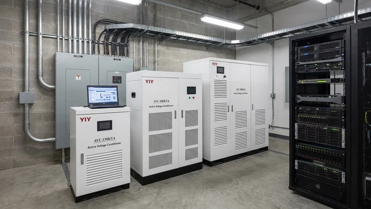
YIY’s stabilizer portfolio covers Servo, Relay, and IGBT solutions across a broad capacity range, with OEM/ODM support for cabinet format, branding, communication, terminal layout, and special environments. For your project, that means you can compare technologies under one engineering review instead of forcing every load into a single stabilizer type.
What Should Your Final RFQ and Supplier Review Include?
Your final RFQ should connect site evidence, load behavior, compliance requirements, and acceptance criteria into one supplier approval file. That protects you from comparing only price and kVA while missing the details that determine whether the stabilizer will work in your installation.
Include these items in the RFQ:
| RFQ item | Why it matters | If you skip it |
|---|---|---|
| Site voltage log | Shows real sag, swell, fluctuation, and unbalance patterns | The quoted input window may not match your site |
| Load list and operating sequence | Identifies simultaneous operation and startup behavior | The stabilizer may be undersized during peak demand |
| Phase and grounding details | Confirms wiring, neutral, and protection design | Installation changes may be required later |
| Inrush and harmonic notes | Helps validate overload curve and derating | Nuisance trips and heating can appear after commissioning |
| Environment details | Captures heat, dust, humidity, altitude, ventilation, and enclosure needs | Electronics may operate outside expected conditions |
| Required documents | Datasheet, wiring diagram, test report, certificates, manual, bypass description | Procurement and commissioning approvals may stall |
| Acceptance criteria | Defines output tolerance, alarms, bypass, commissioning checks, and documentation handover | Disputes become harder to resolve after delivery |
Before you issue the PO, compare the final offer against a structured procurement checklist such as this guide to compare before buying a voltage stabilizer. Even if your project is not exactly 50 kVA, the comparison discipline is useful: match quoted capacity, topology, protection, documentation, and support before you approve the supplier file.
A low-friction next step is a first-pass fit review. Share your load type, phase, approximate kVA, voltage range, site environment, and any existing voltage logs. YIY’s engineering team can then help you decide whether IGBT/PWM static regulation, a servo stabilizer, or another configuration is the better fit.
Frequently Asked Questions
What Load Characteristics Justify an IGBT Based Voltage Stabilizer over Servo or Relay?
Fast-changing, sensitive, or mission-critical loads justify this topology when voltage events can stop production, corrupt output quality, or trigger repeated control faults. Typical fits include CNC machines, medical imaging systems, telecom racks, PLC-controlled automation, semiconductor equipment, and SMPS-heavy panels.
A concrete verification action is to log voltage and current during startup, peak load, and known unstable-grid periods, then compare the disturbance profile with the tolerance of your protected equipment and the stabilizer datasheet.
How Do I Calculate the Correct kVA Rating for High Inrush or Non-Linear Loads?
Base the kVA rating on measured apparent power, power factor, inrush current, harmonics, and thermal derating. For single phase, use kVA = V × A ÷ 1000. For three phase, use kVA = √3 × V × A ÷ 1000.
After the calculation, verify startup current, overload curve, ambient temperature, ventilation, harmonic content, and future expansion. The formula gives your starting capacity; the application review confirms whether that capacity survives real operating conditions.
Is an IGBT Voltage Stabilizer Application Guide PDF Enough for Procurement Approval?
No. Treat an application guide PDF as a reference only. For approval, verify the quoted model datasheet, input voltage window, output tolerance, kVA rating, overload curve, bypass design, protection list, alarm functions, and wiring diagram.
Ask the supplier to mark the exact pages that apply to your ordered configuration, then compare those pages with the quotation, nameplate data, and installation drawing.
What Should I Check in a Static Voltage Stabilizer Circuit Diagram Before Buying?
Check AC input sensing, rectification, DC link, DSP/PWM control, IGBT inverter stage, output filtering, bypass path, protection logic, phase type, grounding method, terminal layout, ventilation clearance, and enclosure/IP requirement.
A block diagram is usually enough for topology confirmation. Suppliers rarely release their internal schematic, yet they should still hand over the installation wiring diagram and protection description.
How Should I Verify IGBT Voltage Rating and Breakdown Voltage Claims?
Ask which IGBT module is fitted (maker and part number), its voltage and current rating, thermal data, cooling method and the approved substitutes. Then ask the supplier to explain how the module rating relates to the DC link voltage, grid input range, surge protection, and overload design.
Final Decision: When Is This Topology the Right Fit?
You should choose an IGBT static voltage stabilizer when the protected load is sensitive, the grid is unstable, and the cost of voltage-related downtime or quality loss justifies tighter electronic regulation. For tolerant loads, relay or servo designs may be more economical. For critical CNC, medical, telecom, automation, electronics, and non-linear loads, this three-phase or single-phase static setup can be the safer engineering choice when validated against your data.
Your final decision should come from measured voltage behavior, real load current, power factor, inrush, harmonics, ambient conditions, documentation quality, and supplier support—not from nominal kVA alone.