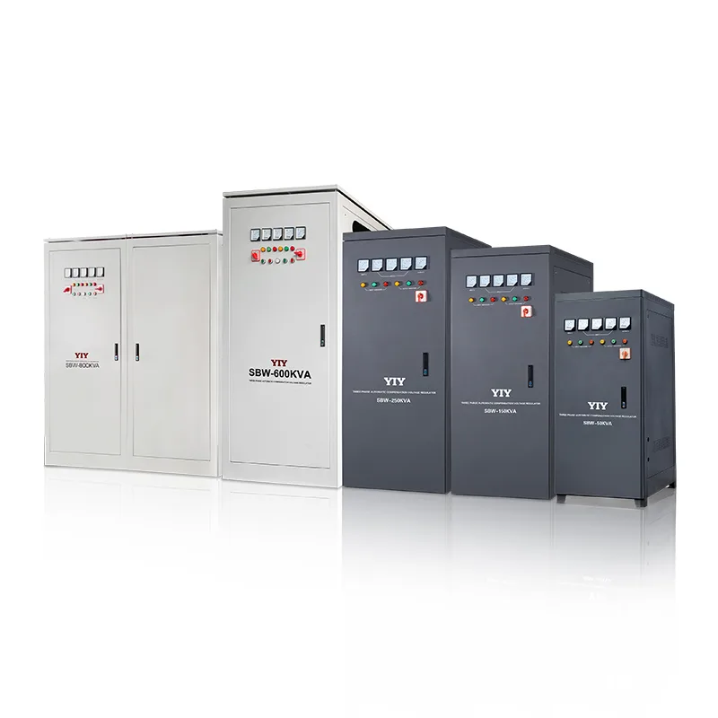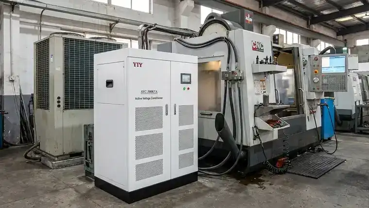
You already know that running sensitive industrial equipment on an unstable grid isn’t just an efficiency issue—it’s a direct threat to your downtime budget and component lifespan. When you weigh single phase voltage vs 3 phase voltage, the delivery architecture you select determines whether your critical assets survive daily line swings or face costly breakdowns. Incorrectly sizing a 10kVA to 30kVA 3-phase stabilizer quickly leads to thermal overload, phase imbalance, and premature motor failure. To avoid that, you need a proven path from raw load data to a precise specification. If your facility demands tight voltage regulation, exploring a dedicated servo voltage stabilizer gives you the continuous correction capacity required for modern automated lines. We’ll break down exactly when to upgrade, how to calculate surge margins correctly, and which control topology protects your specific machinery.
When a 3-Phase Voltage Stabilizer Is Actually Necessary
You must stop forcing single-phase regulators to handle loads they simply cannot support safely. When evaluating single phase voltage vs 3 phase voltage, the underlying distribution method directly dictates your facility’s uptime and thermal resilience. Single-phase systems push all current through two conductors, which creates severe voltage dips during heavy machine startups. In contrast, three-phase power delivery spreads the demand across three synchronized, alternating waveforms to maintain continuous, balanced current. This architectural difference fundamentally determines whether your equipment operates within its design parameters or suffers from chronic under-voltage stress.
The Capacity and Thermal Bottlenecks
If you rely on single-phase regulation for heavy commercial or industrial gear, you will inevitably hit strict thermal limits. Most single-phase units max out around 10kVA, which forces your internal windings and contactors to operate at peak current ratings during regular shifts. Practically speaking, pushing past that limit means your regulator overheats and triggers safety lockouts exactly when your production line needs the most stable voltage. You end up paying for emergency replacements and lost throughput simply because the distribution method lacked the native capacity to handle your load profile.
Operational Risks of Phase Imbalance
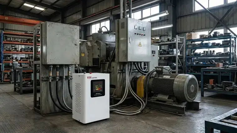
You cannot afford to expose precision assets to prolonged single-phase voltage swings. Your CNC spindles, large rotary compressors, and automated conveyor drives all depend on synchronized grid delivery to maintain tight machining tolerances. When one phase sags on a mismatched supply, your motors overdraw current from the remaining legs, which causes uneven torque, rapid insulation degradation, and sudden controller resets that ruin entire production batches. You’ll quickly find yourself troubleshooting erratic machine behavior instead of managing planned output schedules.
Clear Decision Triggers
You must transition to a three-phase solution as soon as your calculated inductive load consistently surpasses 7kVA or your machinery demands starting currents three times its rated capacity. Practically, securing that three-to-one surge margin prevents you from blowing fuses and tripping main breakers every time a heavy motor kicks on. Tracking recurrent production halts that directly trace back to unmitigated voltage drops gives you a final, undeniable signal to upgrade your power architecture before thermal damage permanently compromises your equipment.
How to Size a 10kVA to 30kVA 3-Phase Stabilizer Correctly
You must translate individual machine nameplates into a precise, actionable kVA rating before you submit any procurement paperwork. Guessing based on rough power estimates guarantees undersized hardware and preventable production stops. Follow this exact workflow to convert your load data into a reliable stabilizer specification that survives daily operational stress.
Calculate Your Base Load and Apply Safety Margins
Start by summing the continuous running kVA of every permanently connected device across all three phases. Once you establish that baseline, multiply the total by 1.20 to 1.30 to lock in your operational safety margin. In practical terms, that 20% to 30% buffer guarantees your regulation circuitry absorbs minor load fluctuations without tripping your facility’s main breakers or dropping output voltage under combined demand. You can see how this applies to mid-range equipment by reviewing a 20kva technical selection guide which breaks down real-world margin applications.
Account for Motor Inrush Current
You must then isolate and calculate the highest cold-start surge in your lineup. Inductive motors routinely pull three to six times their rated capacity during startup, which demands immediate, uncompromised voltage support. Reviewing motor inrush current specifications helps you avoid purchasing a unit that collapses under startup loads by giving you the authoritative surge ratios used in proper capacity planning. Practically, adding this peak surge demand to your baseline calculation prevents your stabilizer from buckling the exact moment your heaviest compressor or spindle kicks online.
Adjust for Input Voltage Windows and Duty Cycles
Your local grid behavior directly dictates how much thermal stress your regulator actually absorbs. When you operate in an extreme input window—such as a facility experiencing daily swings between 15% and 25% deviation—the correction components never reach a stable resting state. In practical terms, relentless voltage hunting forces the unit to run at maximum thermal capacity, meaning you should derate your final selection by another 10% to preserve long-term insulation life. Ignoring this duty cycle reality turns a perfectly sized regulator into a premature hardware failure waiting to happen.
Comparing Stabilization Technologies: Relay, Servo, and IGBT
You need to match the internal control architecture directly to your equipment’s voltage sensitivity before you finalize a purchase. Each regulation method dictates your reactive speed, precision tolerance, and long-term maintenance schedule. Review the core differences below to see which topology aligns with your operational targets.
| Control Technology | Regulation Method | Output Precision | Response Time | Best Application for Your Facility |
|---|---|---|---|---|
| Relay (Electromagnetic) | Steps between fixed transformer taps using contactors | ±5% to ±8% | < 0.05s (noticeable step jumps) | Non-sensitive lighting, basic heating, or low-budget tool runs |
| Servo Motor | Rotating brush hunts across a variable auto-transformer winding | ±0.5% to ±3% | ~1s to 2s (smooth) | CNC machines, medical imaging, and sensitive automated assembly |
| IGBT (Static) | High-speed semiconductor PWM switching with no moving parts | ±1% or tighter | < 20ms (instant) | Mission-critical PLC networks, laser cutters, and cleanroom environments |
Relay-Based Step Correction
You sacrifice smooth regulation to secure a lower upfront capital cost with this architecture. The contactors physically click from tap to tap whenever the grid crosses a set threshold, which means your loads experience noticeable voltage jumps rather than seamless correction. Practically, you should only deploy this on non-critical equipment where occasional flickers won’t interrupt your process or damage sensitive drive electronics. You will also need to budget for periodic contactor replacements as mechanical fatigue sets in over years of switching cycles. If your load profile sits on the lighter end of the spectrum, a dedicated relay voltage stabilizer might cover your basic protection needs.
Servo Motor Continuous Adjustment
You gain near-fluctuation-free delivery with this analog correction method, which quietly maintains tight output precision without jarring your sensitive electronics. A tracking servo motor rotates a carbon brush to find the exact target voltage, which stops sudden torque fluctuations from tripping your variable-frequency drives. Practically, this means your production cycles stay consistent and your tooling life extends, but you must schedule annual maintenance to inspect brush wear and clear carbon dust from the tracking ring. The mechanical architecture delivers exceptional value for most mid-range industrial loads.
IGBT Static Electronic Correction
You eliminate all physical wear points and mechanical latency by switching to a fully static semiconductor architecture. This topology regulates incoming power using ultra-fast electronic switching, which delivers uncompromising stability the exact millisecond grid conditions shift. Practically, you deploy this when even brief voltage dips instantly scrap expensive material batches or trigger cascading network faults across your floor. You trade higher initial investment for completely maintenance-free operation and the tightest possible output tolerance available on the market.
Installation, Site Conditions, and Protection Requirements
You must verify that your physical layout supports continuous heavy-correction duty before you energize the new panel. Skipping thermal and clearance checks guarantees that your precise capacity calculations turn into immediate hardware failures.
Site Preparation and Ventilation
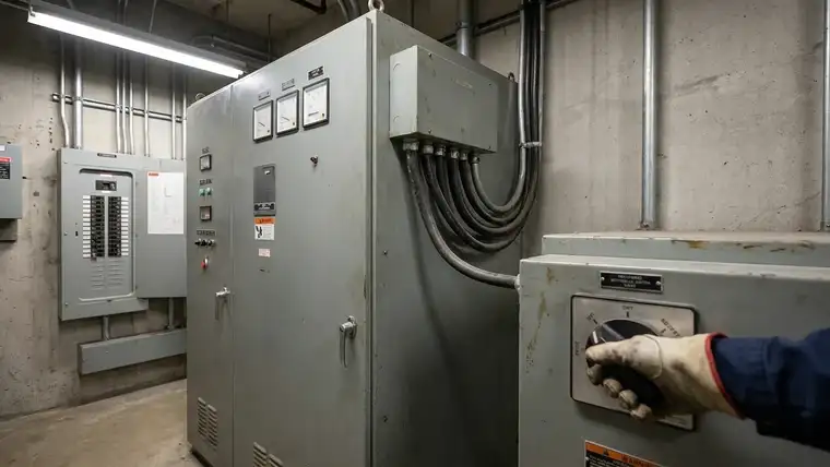
You should position the unit where ambient temperatures stay below 40 °C (104 °F) and fresh air moves freely past every ventilation grille. Respecting this thermal threshold prevents your internal components from overheating during peak shifts. Practically, you need to maintain at least 50 cm (20 inches) of unobstructed clearance on all sides to allow effective heat dissipation. Confining the stabilizer to cramped electrical rooms forces hot air recirculation, which guarantees unnecessary thermal shutdowns and shortens your transformer lifespan. For more on thermal management and how ambient conditions impact regulator performance, review our load sizing guide which explains site-specific derating factors.
Wiring and Phase Balancing
You dictate whether your equipment operates smoothly or trips during startup through your terminal mapping. Strictly follow the L1, L2, L3, and neutral layout to guarantee symmetric current distribution across every output leg. Practically, when you balance these three phases equally, you eliminate the severe micro-sags that quietly degrade precision motor drives over time. Always bond a dedicated grounding conductor to the main bus, and verify that your neutral impedance stays below 0.1 Ω to keep stray fault currents from disrupting your control network and causing erratic machine restarts.
Protection Planning and Commissioning
You need to integrate a dedicated maintenance bypass circuit before you permanently secure the panel doors. This setup isolates the regulator for annual servicing without cutting grid power to your active machinery. Practically, pairing the installation with input and output surge protection instantly absorbs lightning-induced transients before they fry your sensitive PLCs. Finally, you must validate the entire setup against IEC 60038 compliance standards before official commissioning. This means your final tests confirm the stabilizer corrects actual utility swings without destabilizing nearby sensitive electronics or violating grid interconnection rules, giving you documented proof of operational safety.
Frequently Asked Questions
What should you evaluate before choosing single phase voltage vs 3 phase voltage?
You should start by mapping the exact power consumption of every connected asset and comparing that aggregate against your grid’s inherent capacity limits. Single-phase systems typically max out around 10kVA, which makes them prone to severe thermal stress under continuous heavy duty. If your floor relies on multi-spindle CNC lines or heavy compressors, the phase imbalance of a single-phase feed will rapidly degrade your motor windings and drive consistent output failures.
When does three-phase regulation become strictly necessary?
Three-phase regulation becomes mandatory the moment your baseline running load exceeds 7kVA or your starting currents routinely spike to three times rated capacity. While single-phase architecture works fine for office HVAC or small workshop tools, it cannot sustain the synchronized delivery required by large inductive loads. You will face frequent breaker trips and torque fluctuations if you force a mismatched regulator into a high-demand industrial environment.
How should you correctly size or specify a 10kVA to 30kVA stabilizer?
You must calculate the continuous nameplate total across all phases, apply a 20–30% safety margin for operational spikes, and explicitly add the peak inrush current from your heaviest motor. If your local utility swings widely outside standard tolerances, you should derate your final selection by another 10% to ensure the internal windings survive relentless thermal cycling. For a detailed procurement breakdown, consult our 30kva servo stabilizer buying guide before finalizing your RFQ.
Final Thoughts
You don’t have to treat unexpected voltage drops as an unavoidable operational cost when you size and specify your equipment correctly. Matching your continuous running kVA, layering in accurate surge margins, and selecting a control topology based on your actual machine sensitivity eliminates preventable downtime and extends your capital equipment lifespan. If your precision CNC or automated lines require ±1% accuracy, servo-driven models give you the reliable baseline you need. Mission-critical processes that cannot tolerate millisecond dips belong on static IGBT architectures.
Stop guessing and secure your production line against grid instability. Send your finalized load schedule, maximum motor inrush ratings, and site ventilation constraints to our engineering desk today. We will run a thermal and capacity audit and return a precise, spec-ready recommendation within one business day.
For this application, the PWR-3 Three-Phase Servo Voltage Stabilizer is a matched product option worth evaluating.