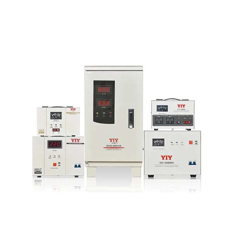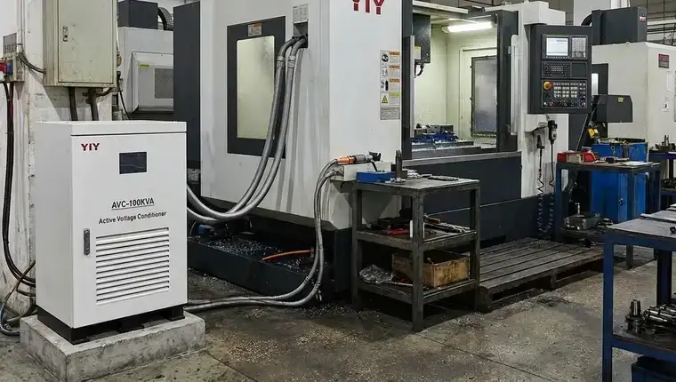
Fluctuating input voltages threaten sensitive industrial loads with accelerated hardware degradation, calibration drift, and unplanned downtime that quickly outweigh initial procurement expenses. The stabimatic 1000 va servo motor voltage stabilizer directly mitigates these risks by deploying a closed-loop, servo-driven autotransformer for continuous, precise power correction, making it a cornerstone of any modern servo voltage stabilizer deployment. Selecting the correct regulation architecture is not a routine purchase; it directly dictates critical equipment lifespan and daily facility uptime.
For other compact options around 1000VA, compare the small voltage stabilizer models, including portable PR and desktop SVC and AVR units.
This guide treats voltage protection as a deliberate technology trade-off rather than a simple spec-matching exercise. We will examine the underlying control mechanics that drive correction speed, map operational scenarios where this topology clearly outperforms relay or solid-state alternatives, and outline the exact sizing parameters and service schedules your engineering team must validate before finalizing a quote.
How the Servo Motor Mechanism Delivers Stable Voltage
The control logic inside a servo-controlled regulator relies on a closed-loop feedback architecture that continuously samples the output line. When input grid voltage fluctuates, a dedicated microprocessor calculates the exact phase and magnitude deviation from the target setpoint and immediately drives a precision motor. This motor physically translates a high-conductivity carbon contact brush along the autotransformer winding to add or subtract voltage without breaking the circuit.
Continuous Brush Correction Versus Stepped Relays
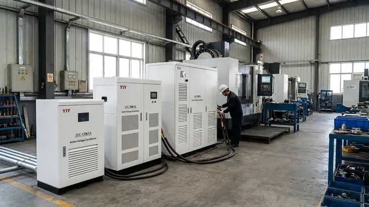
Traditional relay-based stabilizers rely on electromagnetic contactors to jump between fixed transformer taps. Each mechanical tap transition inherently creates a brief power interruption or voltage spike that rapidly degrades downstream drive capacitors and control boards, while a servo mechanism completely eliminates these discrete jumps. Because the brush glides smoothly across the exposed winding segments, the output waveform remains entirely unbroken and free of high-frequency switching harmonics.
Response Benchmarks and Precision Ranges
This analog correction topology delivers baseline performance expectations that align with stringent industrial power quality standards. Modern servo-driven units achieve full response times of ≤1 to 2 seconds after detecting a major grid disturbance while continuously tracking minor variations under highly nonlinear load conditions. Output accuracy consistently locks into a tight precision band between ±0.5% and ±3% depending on model rating, delivering stable regulation without the complex thermal management required by fully static converters.
Preventing Micro-Fluctuations in Critical Loads
The primary engineering advantage of continuous brush adjustment is the absolute elimination of micro-fluctuations during minor grid swings. Relay architectures frequently overshoot during tap changes, generating fast transients that easily breach the hold-up thresholds of delicate programmable logic controllers and sensitive power supplies. Servo correction applies gradual, proportional compensation that keeps delivered voltage strictly within safe tolerances, preventing costly nuisance trips and calibration drift in CNC machining centers, laboratory analyzers, and medical imaging systems.
When Servo Outperforms Relay and Static Topologies
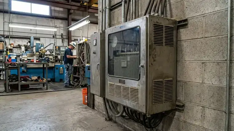
Selecting a voltage regulation architecture is a direct trade-off between initial hardware costs and long-term facility uptime. The following comparison highlights why servo technology consistently serves as the optimal middle ground for industrial applications that demand reliability over raw speed or minimal upfront CAPEX.
| Topology | Typical Response Time | Output Accuracy | Maintenance Cycle | Ideal Application Profile |
|---|---|---|---|---|
| Relay (Tap-Switch) | 0.5 – 2.0 sec | ±5% to ±10% | High (Contactor replacement every 6–12 mos) | Basic HVAC, lighting arrays, resistive heaters |
| Servo Motor | ≤1 – 2 sec | ±0.5% to ±3% | Moderate (Brush inspection every 12–18 mos) | CNC machines, PLC networks, medical imaging |
| Static (IGBT) | < 20 ms | ±0.1% to ±1% | Low (Thermal management & firmware updates) | Cleanrooms, semiconductor fabs, laser systems |
Understanding the practical implications of this data clarifies why the servo design captures the highest market share for precision manufacturing environments. A detailed relay vs servo vs igbt comparison confirms that while IGBT offers superior millisecond response, it introduces disproportionate firmware dependencies and harmonic filtering costs. Conversely, relay-based units fail prematurely in environments with continuous grid volatility. The stabimatic 1000 va servo configuration bridges this performance gap effectively.
Precision, Wear, and Output Smoothness Trade-offs
Relay architectures rely on electromagnetic contactors jumping between discrete transformer taps, creating unavoidable micro-interruptions and voltage spikes during every correction cycle. These transient surges rapidly accelerate capacitor degradation and force premature replacement of downstream programmable logic controllers. By contrast, a servo-driven carbon brush physically glides across exposed copper windings to deliver seamless compensation that eliminates high-frequency switching harmonics and reduces component fatigue.
Cost-Effectiveness Versus Application Limits
Facilities managing standard resistive loads will find relay-based stabilizers entirely cost-effective since minor grid deviations rarely impact their operation. Static solid-state switches provide marginally faster switching but generate substantial thermal loads that demand complex, maintenance-heavy cooling infrastructure. Both architectures consistently fail under continuous heavy-duty conditions, where repetitive thermal cycling or mechanical contactor wear inevitably triggers unplanned production halts.
Mitigating Servo Motor Disadvantages
Critics of servo topology often cite mechanical brush wear as a liability. While continuous physical travel across exposed autotransformer windings does generate predictable contact degradation during chronic grid instability, modern industrial iterations mitigate this through hardened copper-graphite composites, sealed dust-exclusion housings, and intelligent microprocessor tracking. These enhancements extend operational lifespan well beyond 10,000 correction cycles, ensuring maintenance remains scheduled, predictable, and highly cost-efficient compared to catastrophic relay failures.
Key Specification and Maintenance Checkpoints for Buyers
Validating the input voltage window against IEC 60038 standard voltages is the foundational step before procurement. Engineering teams must cross-reference the stabilizer’s nominal correction range with documented local grid variance, accounting for seasonal dips or sudden industrial surges typical in heavy manufacturing zones. Ignoring these ambient electrical realities frequently forces the unit into continuous correction cycles, accelerating component wear and degrading the target ±1% regulation accuracy.
Load Profiling Beyond Nameplate Ratings
Relying solely on total kVA capacity overlooks the transient demands that actually dictate topology selection. Comprehensive industrial voltage stabilizer selection requires engineering teams to calculate peak inrush currents from connected induction motors, ensuring the servo autotransformer can absorb startup spikes without triggering severe voltage droop. Imbalanced three-phase loads introduce internal thermal hotspots, making accurate phase distribution mapping essential before final commissioning.
Harmonic distortion from variable frequency drives (VFDs) and rectifier banks further complicates sizing. Excessive total harmonic distortion (THD) generates parasitic heat in the magnetic core and carbon contact assembly. A properly spec’d unit integrates adequate derating factors and harmonic tolerance thresholds to prevent premature dielectric breakdown. This proactive sizing shields downstream PLCs and precision CNC drives from erratic power signatures that trigger false fault alarms during high-load shifts.
Installation Realities and Routine Maintenance
Physical deployment conditions heavily influence long-term reliability, requiring upfront assessment of ambient temperature, airborne particulates, and dedicated ventilation clearances. Enclosed mechanical rooms demand strictly enforced airflow pathways to dissipate operational heat, preventing servo motor thermal shutdown during extended grid instability. Dust accumulation on the autotransformer surface can rapidly degrade thermal conductivity, making robust filtration enclosures mandatory for unfiltered factory environments.
Maintenance planners must also budget for scheduled carbon brush inspections, typically required every six to twelve months depending on local duty cycles. Integrating a manual bypass switch into the original panel design guarantees zero-downtime servicing during these routine checks or unexpected component failures. This simple architectural addition allows technicians to safely isolate the control circuit while maintaining continuous facility operations for critical production lines.
Matching Operational Constraints to the Stabimatic Line
Facilities operating precision CNC centers, automated optical inspection arrays, or calibrated pharmaceutical environments rely directly on the stabilizer’s tight ±1% regulation band. Procurement audits should prioritize this configuration for equipment where manufacturer warranties explicitly penalize out-of-tolerance power delivery. Engineering teams must deploy this topology wherever downstream load specifications dictate absolute zero tolerance for sustained voltage micro-dips. This architecture proves indispensable for metrology labs and semiconductor fab equipment where calibration drift directly erodes profit margins.
The internal carbon brush assembly introduces a mechanical trade-off that maintenance planners must quantify before final commissioning. As noted in earlier sections, continuous physical travel across exposed windings demands predictable servicing schedules. Modern industrial iterations mitigate degradation through hardened composites and intelligent microprocessor tracking that logs travel distance while scheduling proactive replacements. These diagnostics transform maintenance from reactive troubleshooting into planned operational overhead.
System Architecture and Integration Realities
Integrating the regulator into legacy facility panels requires strict coordination with upstream power sources and downstream distribution networks. Diesel backup generators frequently exhibit reactive voltage droop during heavy inductive motor startups, requiring precise downstream stabilizer placement to smooth dangerous transients before they reach sensitive electronics. Existing electromechanical switchgear must be cross-checked for adequate continuous current ratings and short-circuit withstand capabilities, while dedicated isolation breakers simplify routine testing without disrupting adjacent production lines.
Compatibility with modern backup power infrastructure demands careful topology mapping to eliminate competing regulation algorithms. Pairing an active servo regulator directly with standard line-interactive UPS units frequently triggers unstable hunting as both control loops aggressively chase the same target voltage. Operational best practice dictates positioning the stabilization hardware upstream of online double-conversion systems or locking legacy UPS bypass modules during normal utility service. This hierarchical arrangement eliminates harmonic feedback loops and guarantees pristine input conditioning while isolating emergency battery reserves exclusively for complete mains failures.
Engineering Review and Sizing Support from YIY
Moving from theoretical evaluation to actual procurement requires a manufacturer-backed validation process, not just off-the-shelf spec matching. YIY’s engineering team conducts thorough technical load audits that map real-world inrush currents, phase imbalances, and harmonic distortion profiles. This proactive sizing eliminates costly hardware oversizing and prevents topology mismatches that routinely trigger nuisance trips in downstream CNC networks.
Compliance Framework and Manufacturing Scale
Every stabilizer unit ships with verified compliance to ISO 9001 quality standards and CE marking, ensuring seamless integration into highly regulated industrial grids. Backed by a 30,000㎡ production facility and an annual output exceeding 1,000,000 units, YIY scales this precision consistently across more than 130 export markets, delivering global supply chain reliability alongside localized technical support.
Define Your Next Step Before Quoting
Do not rely on generic catalog quotes for mission-critical power conditioning. Instead, submit your actual load diagrams, historical grid variance data, and environmental constraints directly to our applications team. This targeted specification review guarantees precise topology selection, optimizes total cost of ownership, and prevents costly procurement errors before your facility finalizes the purchase order.
Frequently Asked Questions
What should buyers evaluate before choosing stabimatic 1000 va servo motor voltage stabilizer?
Teams must validate the input correction range against documented grid variance to prevent continuous cycling that accelerates internal wear. Beyond headline kVA ratings, calculate peak inrush currents from connected induction motors and assess harmonic distortion from variable frequency drives. Align unit ventilation requirements and carbon brush inspection schedules with existing maintenance capabilities.
When is stabimatic 1000 va servo motor voltage stabilizer necessary?
This topology protects precision CNC centers, medical imaging arrays, and sensitive PLC networks that cannot tolerate the micro-interruptions or voltage spikes generated by cheaper relay designs. When chronic grid fluctuations trigger equipment faults, unplanned downtime costs quickly eclipse hardware CAPEX. A servo-driven architecture delivers seamless regulation that shields delicate control boards and prevents costly calibration drift.
How should stabimatic 1000 va servo motor voltage stabilizer be sized or specified?
Accurate sizing demands comprehensive load profiling that accounts for motor startup surges and three-phase imbalances rather than relying on nameplate ratings. Incorporate harmonic derating factors for nonlinear loads to prevent core saturation. Always integrate a manual bypass switch directly into the distribution panel to guarantee zero-downtime servicing during scheduled maintenance or unexpected component failures.
Final Thoughts
Selecting the correct voltage regulation architecture ultimately depends on balancing correction speed, output smoothness, and total cost of ownership. While stepped-relay systems suit basic resistive infrastructure and IGBT converters address microsecond-critical applications, the servo-driven topology remains the most balanced solution for precision-critical industrial equipment. It delivers seamless, continuous regulation that shields sensitive CNC controllers, PLC networks, and diagnostic arrays from costly micro-fluctuations and switching transients.
Rather than relying on generic catalog ratings, engineering teams must validate peak inrush currents, harmonic distortion profiles, and site-specific thermal constraints before committing capital. Offer a technical review with YIY to confirm whether servo, relay, or IGBT is the best fit for the application and maintenance context. A targeted technical sizing consultation will guarantee precise topology selection and secure reliable uptime for your most sensitive production assets.
About YIY
Zhejiang Yiyen Holding Group Co., Ltd. (YIY) is a professional voltage stabilizer manufacturer with 16+ years of experience. With a 30,000sqm modern facility and an annual production capacity of 1,000,000+ units, our products are exported to 130+ countries. We provide OEM/ODM customization services and are ISO 9001:2015 certified, committed to delivering stable and reliable voltage protection solutions to global customers.
Contact Us
Email: yiyen@yiyen.com
Phone/WhatsApp: +86 13587452904
Website: https://www.yiyavr.com/
If you found this article helpful, contact us for a sizing review or customized solution.