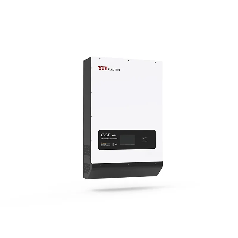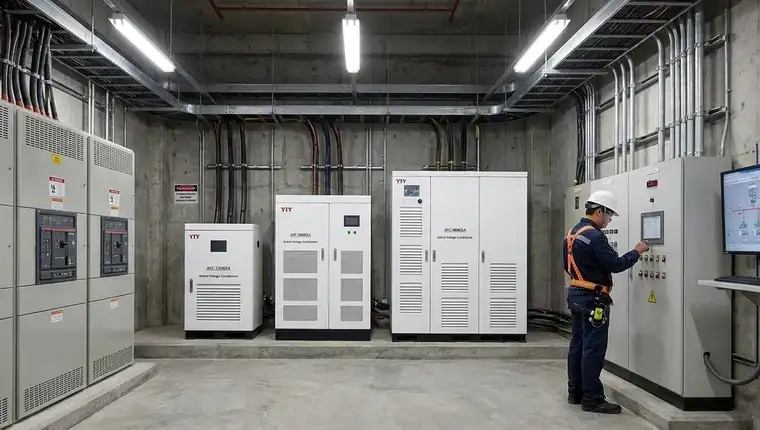
You need a clear diagnostic path when the UPS AVR relay fault, alert lights up your control panel, so you can decide whether to patch your existing hardware or upgrade entirely.
Before you map your load profile against your facility’s actual grid profile, review our three-phase stabilizers to verify your baseline protection tier aligns with industrial phase requirements. For most operations, daily input swings beyond ±10% trigger this fault to shield downstream inverters from catastrophic surges, meaning you can often avoid full capital replacement if you isolate the root cause correctly.
What Actually Triggers This Alert on Your Control Panel?
You encounter this error when your incoming mains drift outside safe operating limits or when your internal electromagnetic switches lose mechanical integrity. The warning activates immediately when your input voltage exceeds a ±10% tolerance band or when fatigued relay coils fail to seat properly, forcing your control board into protective lockout to stop arc-induced damage.
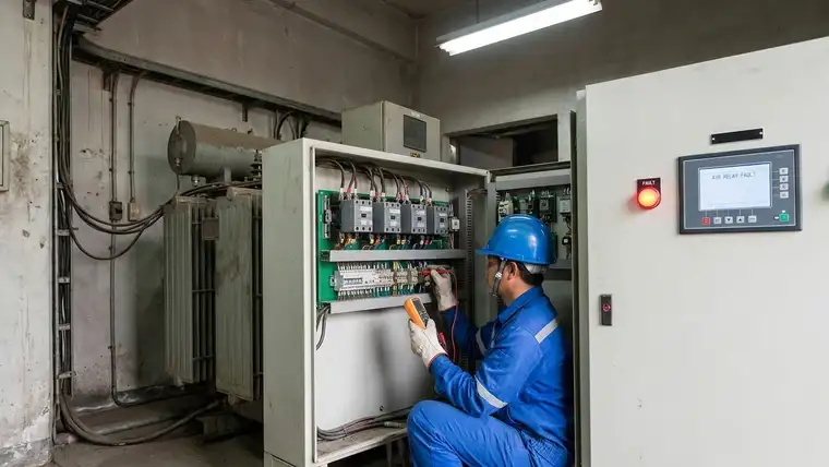
You can isolate the breakdown by tracing the synchronization failure in your feedback loop. Relay-based architectures adjust output by physically jumping between transformer taps, so any coil hesitation or sustained grid instability halts the correction sequence. Per the IEC 60038 standard voltage ranges, industrial protection devices enforce this strict threshold to prevent downstream hardware failure.
What this means for your daily operations is that if your site regularly swings past 207V–253V on a nominal 230V line, your unit will trip alarms long before visible insulation damage reaches your main distribution panel.
Monitor these early indicators to schedule maintenance before unscheduled downtime hits your production line:
– Zero output voltage: Your static bypass engages automatically to isolate critical machinery from unstable mains.
– Frequent switching cycles: Your control board hunts continuously between taps without achieving a locked state.
– Cabinet overheating: Arc-induced thermal stress across pitted contacts exceeds safe dissipation margins.
– Delayed response time: Correction lags past <60ms, exposing sensitive PLCs to damaging micro-dips.
You cannot ignore early contact degradation, as unprotected grid transients typically increase downstream inverter repair expenses by 28% during unstable events. Log your site’s switching frequency and map your incoming drift against your original equipment specs so you know whether you are fighting grid variance or actual hardware fatigue.
How Do You Troubleshoot Without Authorizing a Full Replacement?
You must protect your backup power path by initiating a systematic triage that separates electronic control failures from mechanical wear before purchasing new modules. You restore stability by temporarily bypassing the downstream load, testing coil continuity with a multimeter, and recalibrating your control thresholds rather than immediately authorizing a complete chassis swap.
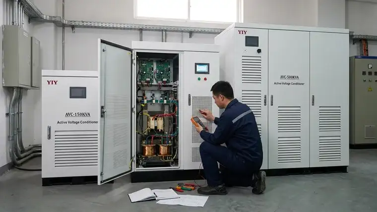
Begin logging live input excursions in real-time. If your mains consistently breach ±10% tolerance, your unit correctly locks out to prevent arc-induced damage, but frequent excursions rapidly degrade switching contacts under thermal stress. You need to measure coil resistance before your maintenance schedule absorbs unnecessary hardware swaps. If your facility operates in a standard commercial environment, reviewing the specifications of a relay voltage stabilizer helps you understand whether discrete tap-switching still matches your baseline variance.
| Diagnostic Action | Expected Indicator | Immediate Correction for You |
|---|---|---|
| Measure input deviation at terminals | E_OVP (Over-Voltage Lockout) |
Reset only after mains normalize; verify upstream tap settings to prevent re-tripping. |
| Test coil continuity with multimeter | R_LOSS (Contact Open/Error) |
Clean oxidized surfaces or replace just the fatigued relay bank instead of the full board. |
| Monitor control board response | DELAY_ERR (Timing Lag) |
Isolate faulty signal drivers and tighten loose terminal screws to restore polling cycles. |
When you install these units in climate-controlled indoor plants rather than extreme outdoor yards, you gain measurable response agility by prioritizing thermal dissipation over heavy environmental sealing. Correcting voltage sags in under 60 milliseconds ensures your automated PLCs never register a brownout before the regulator locks the transformer tap, preserving your daily output yields without expensive servo retrofits.
Why Do Electromagnetic Control Circuits Degrade Under Heavy Load Cycling?
You face this failure sequence when your stabilizer attempts to correct fluctuating mains using discrete mechanical steps instead of continuous tracking. These faults emerge because inherent sensing delays force your control board to hunt aggressively across transformer taps, rapidly accelerating contact pitting when incoming grid variance exceeds your unit’s compensation bandwidth.
The microprocessor polling intervals combined with physical coil induction create a cumulative latency gap. When your supply oscillates outside ±5–8% precision, these lags trigger rapid cycling that pits your contact surfaces faster than the system can safely dissipate heat. What this means practically for your maintenance schedule is that chasing minor grid dips mechanically exhausts your switching bank before your control logic can safely de-energize the coils, leaving you with repeated COIL_TIMEOUT or ERR_OVERHEAT warnings.
Manufacturing lines compliant with ISO 9001:2015 Quality Management mitigate early fatigue by enforcing strict dimensional tolerances during relay assembly and contact plating. If your installation faces conductive dust or corrosive humidity, you must specify IP54 enclosures with forced airflow to prevent PCB bridging. What this means for your facility layout is that routing these alarms directly into your SCADA logs transforms reactive break-fix cycles into predictive maintenance, preventing the cost spikes typical of unprotected bypass failures.
Which Protection Topology Best Handles Your Actual Grid Conditions?
You should evaluate your exact load profile and local grid variance before authorizing a capacity upgrade or changing your correction architecture. You need a brushless servo configuration for facilities facing daily grid fluctuations beyond ±15%, while standard relay architectures remain viable only for stable baselines that stay within a ±10% bandwidth.
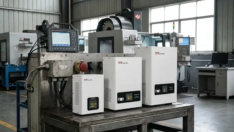
Before you commit procurement capital, map your requirements against a four-point matrix: required kVA capacity with a 25% safety margin, incoming voltage bandwidth, environmental constraints, and phase topology. Review our sizing and specification protocols to ensure you account for motor start-up surges that typically exceed steady-state running loads. What this means for your purchasing decision is that undersizing your protection tier by 10% can actually reduce its lifespan by half when transient inrush currents repeatedly stress internal components.
| Architecture | Practical Input Tolerance | Correction Response | Best Fit for Your Application |
|---|---|---|---|
| Relay AVR | ±5–10% | <60ms | Stable commercial loads where budget matters and daily swings remain predictable. |
| Servo Stabilizer | ±15–40% | <200ms | Heavy industrial zones with severe grid swings where continuous brush tracking prevents mechanical wear. |
| IGBT/Static AVR | ±30–50% | <15ms | Precision CNC or medical imaging lines requiring zero-interruption microsecond compensation. |
A 2026 engineering audit shows that forcing a relay unit to manage fluctuation-heavy zones increases your downstream inverter repair expenses by 28%. What this translates to in your daily operations is that if your supply consistently drops below 180V, a mechanical contactor arcs and overheats faster than your control logic can reset, directly impacting your line OEE scores and forcing costly bypass modes.
When you match your topology to actual grid variance instead of nominal ratings, you transform voltage correction from a recurring repair line into a predictable operational cost.
What Pre-Commissioning Checks Must You Complete?
You finalize deployment by validating coil health and confirming environmental sealing before you close the main breaker. You run sequential validation steps that verify electromagnetic continuity, align tap calibration against live grid drift, route fault codes to your SCADA, and confirm enclosure IP ratings to survive daily operational stress.
- Verify Electromagnetic Coil Continuity: You must measure winding resistance across each relay bank before energizing loads. This confirms your contactors will seat cleanly without arcing, directly preventing thermal shutdowns during heavy cycle events.
- Cross-Check Tap Alignment Against Standards: You compare your baseline steady-state output against ±10% variance limits. If your mains regularly exceed this window during commissioning, your unit correctly locks out to protect downstream inverters. What this means for your startup sequence is that you should normalize upstream grid conditions first rather than forcing the stabilizer to compensate permanently.
- Route Alarm Visibility to Control Rooms: You integrate
ERR_OVERHEATandCYCLE_EXCESScodes directly into your plant maintenance dashboard. Real-time logging prevents the 28% repair overhead spikes that happen when early switching delays go unnoticed until hardware fails. - Confirm Environmental Sealing Matches Floor Conditions: You verify at least an IP54 enclosure in conductive dust zones. Without active ventilation planning, standard indoor frames trap heat near transformer windings, so you must upgrade chassis airflow or relocate the cabinet before high-cycle machinery reaches full load.
Frequently Asked Questions
What Input Voltage Tolerance Thresholds Trigger an AVR Relay Alarm per International IEC Standards?
The protective interrupt activates immediately when your incoming mains breach the ±10% nominal range specified by international standards. Sustained deviations beyond this limit force your control board to halt tap-switching to prevent downstream inverter damage. You should verify your local grid baseline against these tolerances before reinitializing the unit to avoid repeated lockout cycles during surge events.
Can UPS Relay Faults Be Repaired on-Site, or Does the Control Board Require Full Module Replacement?
You can often restore full functionality on-site by testing electromagnetic coil continuity with a multimeter and replacing only the fatigued relay bank or cleaning oxidized contact surfaces. A complete control board swap becomes necessary only when PCB signal drivers show irreversible burn traces or timing lags consistently exceed safe correction windows. Isolating the specific failure layer prevents unnecessary capital expenditure on complete unit replacements.
How Does Relay-Based Stabilization Compare to Servo Mechanisms for Fluctuating Industrial Grid Conditions?
Relay architectures deliver faster initial correction under 60 milliseconds but accumulate mechanical contact wear when daily voltage swings consistently exceed ±15%, whereas brushless servo configurations continuously track severe grid variance without moving contact points. You should reserve discrete tap-switching for stable baselines and deploy continuous-motion topologies when your facility faces heavy industrial load cycling or extreme input instability. Matching topology to your actual grid profile directly reduces your long-term maintenance overhead.
What Should Your Next Engineering Step Be?
You should validate your incoming voltage logs against established tolerance thresholds before defaulting to identical relay replacements. Daily mains swings that consistently breach the ±10% bandwidth rapidly accelerate electromagnetic contact degradation and elevate unplanned downtime costs across your production lines. Aligning this protection tier with your actual operational risk profile prevents the cascading inverter repairs that drain annual maintenance budgets.
We highly recommend using our structured framework to compare before buying a voltage stabilizer, which helps you quantify topology tradeoffs, review historical fault logs, and finalize a targeted procurement shortlist tailored specifically to your facility’s load characteristics.
Related AVR Topology and Usage Question Guides
Compare relay, servo, and IGBT regulator choices, then browse related usage questions for troubleshooting and selection context.