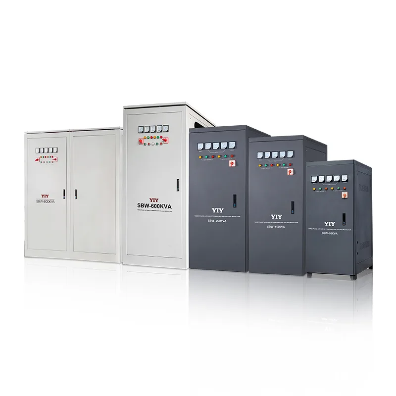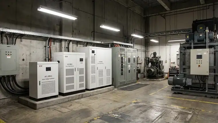
A 3 phase stabilizer for lift should be sized for motor starting current, not nameplate kW, and must cover your measured input-voltage window. This guide covers lift voltage risks, sizing, servo versus IGBT topology, final specification checks, and what to put in your RFQ.
If you are comparing three-phase stabilizers for a lift project, start with the load and grid data below.
What Voltage Risks Do Your Elevator Systems Face in Industrial Power Networks?
Map phase unbalance and starting-current events before procurement, because lift drives and controllers are the first loads to trip when supply voltage drifts.
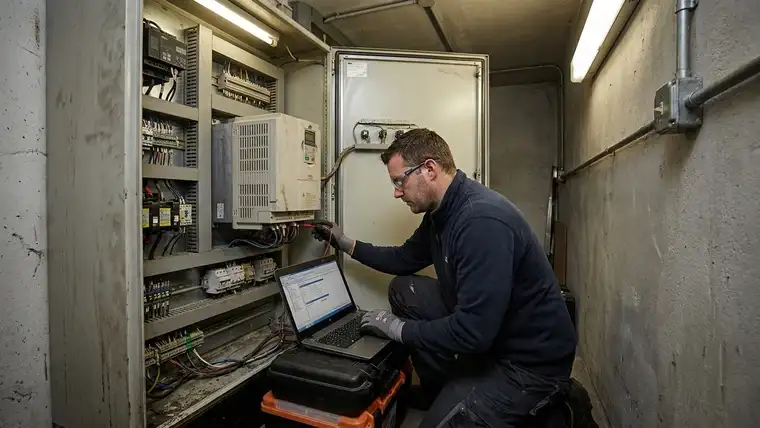
Lift motors draw several times their rated current during each acceleration and brake release. Drive cabinets then see repeated short sags, which stress bus capacitors and control electronics over time.
That is why sizing protection only for steady-state kW tends to produce nuisance trips at peak traffic. Voltage asymmetry across incoming lines adds uneven heating in motor windings and erratic control signals, so check phase balance as well as the average voltage.
For budgeting, price each failure mode against your own downtime and callback costs. The exposure goes beyond the hardware quote: board replacements and unexplained leveling faults show up later as service cost.
A unit with event logging and alarm outputs that feed your BMS gives your maintenance team an early warning before a fault trip.
How Do You Size and Deploy a Line Conditioner to Handle Elevator Inrush Safely?
Size the stabilizer for peak starting kVA rather than running demand, then agree the overload margin with the supplier against measured site data.
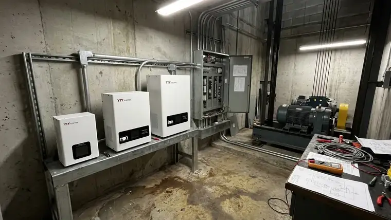
Motor nameplate ratings ignore the duty cycle that actually drives voltage stability. A regulator sized only for continuous running kVA can be overloaded at every start in a busy lift group.
To find the real requirement, take steady-state kVA, apply the starting-current multiplier you measured or the drive maker states, and check the result against the unit’s short-term overload rating. That keeps the car moving while the grid recovers from the start sag.
Real load profiling replaces guesswork. Clamp a three-phase analyzer at the main feeder and record a full operating day to capture actual peak events instead of averages. The 3 phase main line stabilizer sizing guide walks through the same measured approach for a whole building feed.
| Capacity Tier | Matching Logic | Operational Risk for You |
|---|---|---|
| Undersized | Sized to running load only | You face frequent nuisance trips and contactor welds during rush hours. |
| Correctly Matched | Covers measured start peaks with an agreed overload margin | You gain stable output with optimized thermal headroom. |
| Oversized | Margin far beyond measured peaks | You absorb higher no-load losses and deal with an oversized footprint. |
For grouped lift drives, sum the loads that can run at the same time first, then apply a diversity factor so you do not stack every start peak at once.
Check that the input correction window covers your local grid, using the nominal voltage bands in IEC 60038:2009 as the reference point. Install with short, segregated terminal runs so heavy starts cause as little extra drop as possible.
How Does Topology Selection Impact Your Drive Compatibility and Maintenance Schedule?
Servo units correct by moving a carbon brush on a variable transformer, so they react in seconds; IGBT conditioners such as YIY’s AVC reshape the output electronically and complete correction within half a cycle.
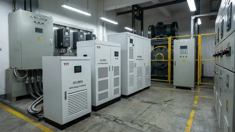
Match regulation speed to how your VFD and controller tolerate short sags. A mechanical regulator cannot chase sub-cycle dips, so the drive sees them; a solid-state unit can correct before the drive registers the drop.
For many lift groups, a servo unit is still the cost-effective choice if dips are slow and the drive rides through short events. Choose IGBT when your drive logs undervoltage faults on fast dips.
| Performance Metric | Carbon-Brush Servo | Solid-State IGBT/PWM |
|---|---|---|
| Response Time | Seconds (YIY TWS servo: ≤2 s) | Within half a cycle (YIY AVC) |
| Thermal Management | Forced air required; brush friction adds heat | Solid-state heatsinks; check derating at your room temperature |
| Harmonic Filtering | Low; VFD passthrough noise accelerates wear | Depends on design; ask for test data with drive loads |
| Maintenance Frequency | Periodic brush and drive inspection | No moving parts; fan and capacitor checks |
For high-cycle sites, the 20kVA voltage stabilizer technical guide shows how the same topology choice scales across capacity tiers.
In your specification, ask for dip immunity test evidence referencing IEC 61000-4-11:2020, and confirm the unit’s harmonic behavior with drive loads on the supplier’s test report. Specify an enclosure IP rating that suits the machine room and ask whether alarm or communication outputs are available.
Which Operational Metrics and Environmental Constraints Should Dictate Your Final Specification?
Lock in four checks: the continuous input voltage window, output accuracy, an enclosure rating for your machine room, and cooling capacity matched to your lift duty cycle.
Use the table to drop units that can’t handle lift-specific stress.
| Checkpoint | Specification Requirement | Plain-Language Implication for You |
|---|---|---|
| Input Voltage Window | Covers the minimum and maximum in your measured voltage log, with margin | If your correction band is too narrow, your unit will trip during morning rush hours instead of regulating the sag. |
| Output Accuracy | Tolerance stated per phase at full load | Controllers need stable supply rails; drift outside the drive’s tolerance shows up as leveling faults and drive alarms. |
| Enclosure & Cooling | IP rating suited to the machine room, with cooling matched to ambient temperature | Dust and humidity shorten component life, and repeated starts need thermal headroom. |
| Bypass Integration | Manual or automatic bypass switch rated for full load current | Lets lifts keep running on raw supply while the stabilizer is serviced. |
Cross-reference input ranges against utility logs rather than nominal values, since industrial-zone grids often drift beyond nameplate assumptions. Matching enclosure ratings to real ambient conditions is also central to any industrial voltage stabilizer selection.
If the machine room runs hot, specify forced-air cooling or a derated unit so thermal protection doesn’t cause shutdowns. Where the cabinet sits next to lift motors, use vibration isolation to keep bus-bar connections from loosening.
Skipping a bypass switch or accepting a loose output tolerance to save capital shifts the cost into downtime. Factory burn-in testing under an ISO 9001:2015 quality system helps catch early failures before the unit reaches site.
Write these thresholds into your acceptance protocol, because field changes after installation rarely close the gap without a retrofit.
What Should Your Lift Stabilizer RFQ Include?
Make the RFQ specific enough that suppliers can’t quote on kVA and price alone. Each line below lets the supplier check load behavior, grid conditions, protection, and installation before recommending a model.
| RFQ item | What to send | What it helps verify |
|---|---|---|
| Lift load list | Motor kW/HP, rated current, controller/VFD details, brake and door loads | Whether capacity covers the complete protected load |
| Starting data | Starting current, soft-start method, VFD presence, duty cycle | Whether start sags will overload the unit |
| Voltage log | Minimum, maximum and average input voltage, frequency, phase condition | Whether the input range is wide enough |
| Protection package | Phase loss, phase sequence, over/under-voltage, overload, short-circuit, bypass | Whether commissioning and maintenance needs are met |
| Installation environment | Temperature, humidity, dust, ventilation, cabinet access, grounding, cable size | Whether enclosure, cooling and service access suit the room |
| Documentation | Wiring diagram, test report, manual, certificate copies | Whether installation and handover can proceed |
Also ask whether the unit corrects all three phases together or each phase independently. On a heavily unbalanced supply, a balanced average can hide one weak phase, and independent correction is the safer pick.
For hot or dusty machine rooms, compare cooling options in the oil-cooled three-phase servo stabilizer spec guide before final approval.
Frequently Asked Questions
What Happens If You Wire 3-Phase Wrong?
Wrong three-phase wiring can cause phase-sequence faults, reversed motor rotation, controller alarms, overheating or a failed lift commissioning. Before energizing, have a qualified electrician confirm R/Y/B order with a phase-sequence meter, check neutral and earth continuity, torque the terminals and match input/output labels to the wiring diagram.
Is a Servo Stabilizer Enough If Your Site Has Blackouts?
No. A stabilizer regulates voltage within its correction range but stores no energy, so it can’t carry a lift through an outage. Specify UPS or backup power separately, and coordinate the stabilizer, UPS, generator and drive protection settings; the UPS vs stabilizer guide covers where each fits.
What Is the Difference Between a Single-Phase and 3 Phase Stabilizer?
A single-phase unit corrects one live line; a three-phase unit corrects all three, which a three-phase lift motor needs to avoid unbalanced heating. Ask the supplier to state output accuracy per phase and whether phases are corrected independently.
How Should the Bypass Be Arranged for Lift Maintenance?
Pick a full-current-rated bypass, ideally interlocked so it can’t connect input and output at the same moment. Request the bypass wiring diagram and confirm your maintenance team can isolate the stabilizer without shutting down the lift.
Final Thoughts
Size a lift stabilizer from starting current and measured grid data, then choose servo or IGBT by how fast your dips are. For most industrial lift groups, the SBW three-phase servo stabilizer is a sensible starting point for a sizing review.