Choosing the right voltage stabilizer for a solar panel system is not a matter of guesswork. Undersized units trip under load. Oversized units waste capital. This guide provides the exact sizing methodology, product recommendations, and installation practices that professional solar installers and procurement teams need to get it right the first time.
Why Solar Panel Systems Need Dedicated Voltage Stabilization
Solar photovoltaic systems inject power into a grid that was never designed to handle distributed, variable generation. When cloud cover drops irradiance by 60% in seconds, the inverter output swings accordingly. The grid side responds with voltage sags and surges that exceed the inverter’s operating window. The result: protective shutdowns, anti-islanding trips, and wasted generation capacity.
Industry data consistently shows that inverter shutdowns caused by voltage excursions account for 5-15% of annual energy loss in residential and small commercial PV installations. In regions with weak grid infrastructure — common across Southeast Asia, Africa, and parts of Latin America — losses can exceed 20%.
A dedicated voltage stabilizer installed on the AC output side of the inverter absorbs these fluctuations before they reach the inverter’s protection thresholds. The inverter stays online. Generation continues. Payback periods shorten.
For a detailed technical analysis of PV voltage challenges — including reverse power flow, harmonic distortion, and voltage rise phenomena — refer to our comprehensive hub article.
Residential PV Systems (1-10 kW): Sizing and Selection
Capacity Calculation
The fundamental sizing rule for residential PV voltage stabilizers:
Stabilizer rating (KVA) = Inverter AC output (kW) x 1.25 safety factor
This 25% headroom accounts for three factors: inverter inrush current during startup, reactive power demand from motor loads (refrigerators, HVAC), and voltage correction overhead. For installations with significant motor loads, increase the safety factor to 1.5.
Residential PV systems in most markets operate at single-phase 220V/230V, 50Hz or 60Hz. The stabilizer must match both the voltage standard and frequency of the local grid.
Recommended Products
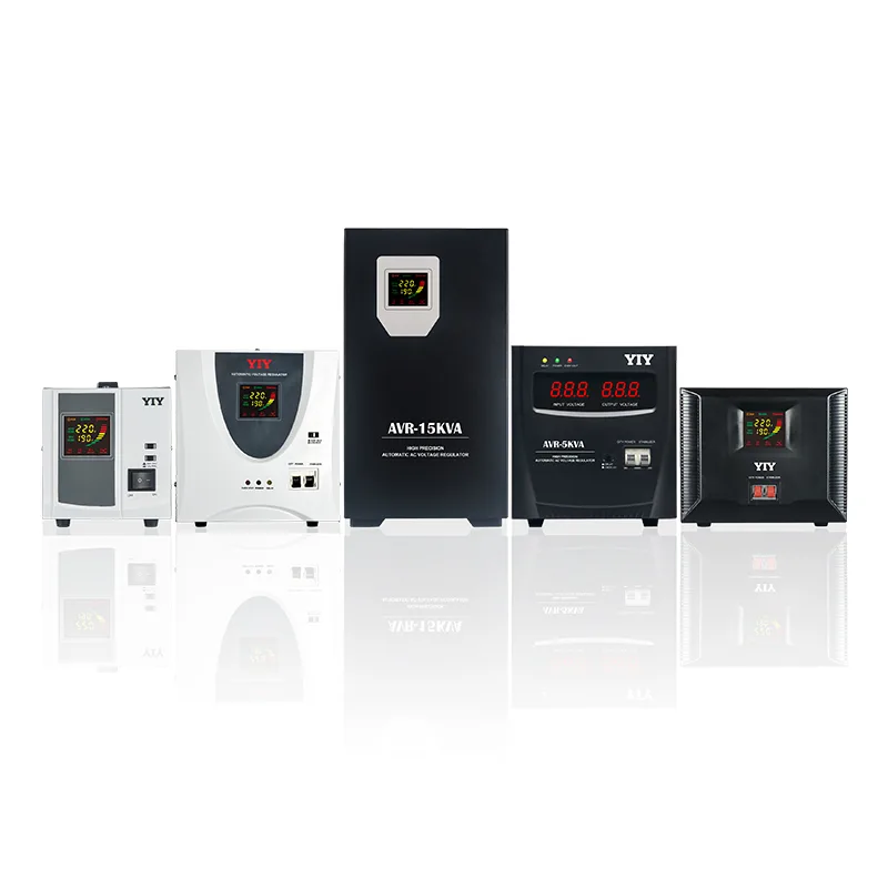
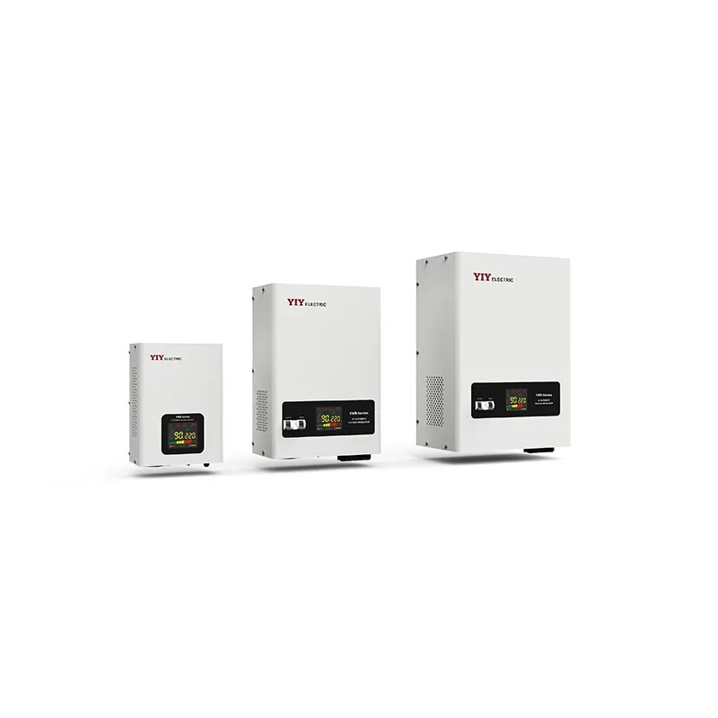
TWS Wall-Mounted Servo Stabilizer (500VA – 5KVA)
The TWS wall-mounted servo stabilizer is purpose-built for space-constrained residential installations. Key specifications:
- Output accuracy: +/-3%
- Input voltage range: 80-260V (handles severe grid instability)
- Mounting: wall-mount bracket — no floor space required
- Noise level: silent operation via servo motor mechanism
- Best fit: 1-5 kW home PV systems
The wall-mount form factor is a decisive advantage in residential settings where the stabilizer shares space with the inverter, distribution board, and meter in a utility closet or garage wall.
SVC Servo Stabilizer (0.5 – 30KVA)
The SVC servo voltage stabilizer offers wider capacity coverage for larger residential or home-office PV systems:
- Output accuracy: +/-1-3% (adjustable)
- Form factor: floor standing, vertical cabinet
- Capacity range: 0.5-30KVA — covers the full residential spectrum
- Best fit: 5-10 kW home or home-office PV systems
The SVC’s tighter accuracy tolerance (+/-1%) makes it the preferred choice for installations feeding sensitive electronics — home offices, medical equipment, or networking infrastructure.
AVR Relay Voltage Stabilizer (500VA – 10KVA)
The AVR relay voltage stabilizer provides the budget-friendly entry point:
- Output accuracy: +/-8%
- Response type: relay-switched tap (step correction)
- Cost: lowest unit price in the range
- Response time: fast step response (relay switching)
- Best fit: budget-conscious installations with less sensitive loads (lighting, water heaters, basic appliances)
The +/-8% accuracy is adequate when connected loads can tolerate wider voltage variation. It is not recommended for sensitive electronics or inverters with narrow input voltage windows.
Residential Product Comparison
| Feature | TWS Wall-Mounted | SVC Servo | AVR Relay |
|---|---|---|---|
| Output Accuracy | +/-3% | +/-1-3% | +/-8% |
| Regulation Type | Servo motor | Servo motor | Relay-switched tap |
| Input Range | 80-260V | 150-250V (standard) | 140-260V |
| Capacity Range | 500VA – 5KVA | 0.5 – 30KVA | 500VA – 10KVA |
| Mounting | Wall-mount | Floor standing | Floor standing / shelf |
| Noise Level | Silent | Low | Click noise on switching |
| Best PV Capacity | 1-5 kW | 5-10 kW | 1-5 kW (non-sensitive loads) |
| Relative Cost | Medium | Medium-High | Low |
Small Commercial PV Systems (10-50 kW): Three-Phase Solutions
Commercial PV installations from 10 kW upward typically operate on three-phase 380V/400V power distribution. The stabilizer must regulate all three phases, and — critically — must handle phase imbalance, which is common in mixed commercial loads (lighting on one phase, HVAC compressor on another, production equipment on the third).
PRO-3 Three-Phase Servo Stabilizer (15-200KVA)
The PRO-3 three-phase servo stabilizer is the industrial-grade solution for demanding commercial PV installations:
- Output accuracy: +/-1-3%
- Core technology: toroidal transformer — higher efficiency, lower losses
- Monitoring: RS485 communication port for remote monitoring and SCADA integration
- Capacity range: 15-200KVA
- Best fit: 20-50 kW commercial PV systems, manufacturing facilities, commercial complexes
The RS485 interface is a key differentiator for commercial installations. Facility managers can monitor voltage levels, load percentage, and fault status from a central building management system (BMS) — essential for preventive maintenance and SLA compliance.
SVC-3 Three-Phase Servo Stabilizer (3-90KVA)
The SVC-3 three-phase servo stabilizer covers the mid-range commercial segment:
- Output accuracy: +/-3%
- Independent per-phase regulation — each phase is corrected individually
- Capacity range: 3-90KVA
- Best fit: 10-30 kW commercial PV systems, small workshops, retail complexes
Independent per-phase regulation is particularly valuable when phase loads are significantly unbalanced — a common scenario in retail environments where lighting, refrigeration, and HVAC draw unevenly across phases.
When to Choose PRO-3 vs. SVC-3
| Decision Factor | PRO-3 | SVC-3 |
|---|---|---|
| PV System Size | 20-50+ kW | 10-30 kW |
| Remote Monitoring Required | Yes (RS485 built-in) | Optional / not standard |
| Toroidal Transformer Core | Yes | No (conventional core) |
| Best Application | Factories, commercial complexes, data centers | Workshops, retail, small offices |
| Budget Priority | Performance and monitoring | Value and adequate performance |
Inverter Compatibility Checklist
Not every stabilizer-inverter combination works without issues. Before specifying a voltage stabilizer for any solar panel system, verify these five compatibility checkpoints:
- Voltage Window Match: The stabilizer’s output voltage range must fall within the inverter’s AC input tolerance. If the inverter accepts 180-270V and the stabilizer outputs 220V +/-3% (213-227V), there is comfortable overlap. If the stabilizer is only +/-8%, verify the worst-case output stays within the inverter’s window.
- Frequency Tolerance: Grid-tied inverters synchronize to grid frequency (50Hz or 60Hz). The stabilizer must be frequency-transparent — it should not introduce frequency distortion. All servo-type stabilizers (TWS, SVC, PRO-3, SVC-3) are frequency-transparent by design.
- Anti-Islanding Behavior: Grid-tied inverters include anti-islanding protection that shuts down the inverter when grid power is lost. The stabilizer must not interfere with this detection. Install the stabilizer between the inverter AC output and the grid, not in a configuration that could mask a grid outage from the inverter.
- Grounding Scheme: Verify that the stabilizer’s grounding configuration is compatible with the site’s earthing system (TN-S, TN-C-S, TT, or IT). Mismatched grounding can cause nuisance RCD trips or compromise safety.
- Communication Protocol: For monitored installations, confirm that the stabilizer’s communication protocol (RS485, Modbus RTU) is compatible with the site’s BMS or monitoring platform.
Major Inverter Brand Compatibility Notes
| Inverter Brand | Typical AC Voltage Tolerance | Stabilizer Notes |
|---|---|---|
| SMA (Sunny Boy / Tripower) | 180-270V (single-phase) | Wide tolerance. Servo stabilizers (+/-3%) provide comfortable margin. AVR (+/-8%) is acceptable. |
| Huawei (SUN2000 series) | 180-270V (single-phase), 310-478V (three-phase) | Built-in voltage monitoring. External stabilizer prevents repeated grid-fault logging. Servo type recommended. |
| Growatt (MIN / MID / MAX) | 175-275V (single-phase) | Compatible with all YIY stabilizer types. Narrower tolerance on older models — verify datasheet. |
| Sungrow (SG series) | 180-270V (single-phase), 310-478V (three-phase) | RS485 monitoring available on commercial models — pair with PRO-3 for unified monitoring. |
Installation Best Practices for PV Voltage Stabilizers
Wiring Sequence
This is the single most critical installation detail. The correct wiring sequence is:
Grid / Utility Supply → Voltage Stabilizer → Inverter AC Output / Distribution Panel
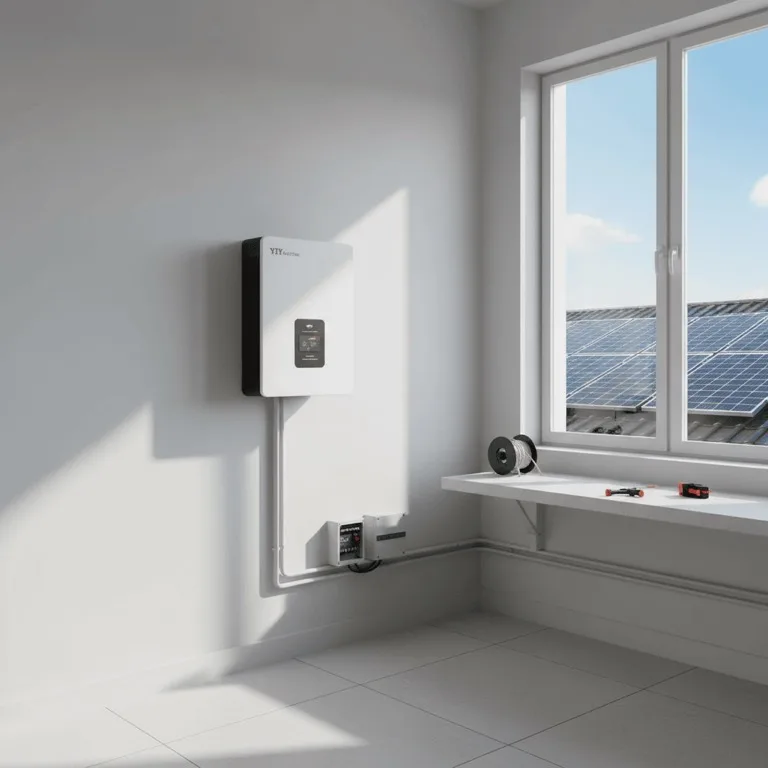
The stabilizer sits on the AC side, between the grid connection point and the inverter’s AC output terminal (or the main distribution panel). It stabilizes the voltage that the inverter “sees” from the grid, ensuring the inverter’s grid-tie connection remains within acceptable parameters.
Do NOT install a voltage stabilizer between the solar panels and the inverter’s DC input. The DC side operates at variable voltage by design (MPPT tracking). Inserting a stabilizer on the DC side would interfere with the inverter’s maximum power point tracking algorithm and reduce system efficiency.
Grounding Requirements
- Connect the stabilizer chassis to the site’s protective earth (PE) bus.
- Ensure the earth conductor cross-section meets local electrical code requirements (minimum 4mm2 copper for residential, 10mm2 for commercial).
- Verify earth continuity with a ground resistance tester — target less than 5 ohms.
- For three-phase installations, connect the neutral bus to the stabilizer’s neutral terminal with appropriately rated conductors.
IP Rating for Outdoor and Semi-Outdoor Installations
- Indoor installation (utility room, garage): IP20 is sufficient. All standard YIY models meet this requirement.
- Semi-outdoor (covered carport, open-sided shelter): IP44 minimum. Use a weatherproof enclosure if the standard model does not carry this rating.
- Fully outdoor: IP54 or higher. Consider a purpose-built outdoor enclosure with ventilation fans and drain holes.
Bypass Switch Recommendation
Every PV stabilizer installation should include a manual bypass switch. This allows the system to continue operating (without voltage regulation) during stabilizer maintenance or in the event of a stabilizer fault. The bypass switch should be rated for the full load current and installed in a clearly labeled, accessible enclosure.
A bypass switch also simplifies troubleshooting: if the inverter trips with the stabilizer inline but runs normally on bypass, the issue is in the stabilizer configuration, not the inverter or grid.
YIY Recommended Configurations
Based on field deployment data across 130+ countries, the following table provides our standard sizing recommendations for solar voltage regulator installations:
| PV System Capacity | Recommended Stabilizer | Stabilizer Capacity | Installation Type |
|---|---|---|---|
| 1-3 kW | TWS Wall-Mounted Servo | 3 KVA | Wall-mount, single-phase |
| 3-5 kW | TWS 5KVA or SVC 5KVA | 5 KVA | Wall-mount or floor, single-phase |
| 5-10 kW | SVC Servo | 10 KVA | Floor standing, single-phase |
| 10-20 kW | SVC-3 20KVA or PRO-3 20KVA | 20 KVA | Floor standing, three-phase |
| 20-50 kW | PRO-3 Servo | 50 KVA | Floor standing, three-phase |
Sizing note: These recommendations apply the 1.25x safety factor. For installations with significant motor loads (workshops, agricultural processing), apply a 1.5x factor and move up one capacity tier.
For a broader overview of stabilizer selection across all application types, see our voltage stabilizer selection guide.
Frequently Asked Questions
Can I install a voltage stabilizer between solar panels and the inverter?
No. The voltage stabilizer must be installed on the AC output side of the inverter, between the inverter and the distribution panel (or grid connection point). The DC side between the solar panels and the inverter operates at variable voltage by design — this is how MPPT (Maximum Power Point Tracking) works. Installing a stabilizer on the DC side would disrupt the MPPT algorithm and reduce energy harvest.
What size stabilizer do I need for a 5 kW solar system?
Apply the standard sizing formula: 5 kW x 1.25 safety factor = 6.25 KVA minimum. Since stabilizers are sold in standard sizes, a 7.5 KVA or 10 KVA unit is the practical choice. We recommend the YIY SVC 10KVA for 5 kW PV systems — it provides comfortable headroom for motor starting currents and future load growth, with +/-1-3% output accuracy that keeps inverters operating reliably.
Do I need a stabilizer if my inverter has built-in voltage regulation?
Modern grid-tied inverters regulate their own DC-to-AC conversion output, but they cannot correct voltage problems on the grid side. If your area experiences frequent voltage fluctuations exceeding +/-10% of nominal (common in rural areas, developing grid infrastructure, or end-of-line connections), an external stabilizer protects both the inverter and all connected loads. The stabilizer ensures the grid voltage presented to the inverter stays within its operating window, preventing protective shutdowns and maximizing generation uptime.
What happens if the stabilizer is undersized for my PV system?
An undersized stabilizer will either trip on overload during peak generation (shutting down the system) or overheat from sustained operation above rated capacity, reducing its lifespan. Neither scenario is acceptable. Always size to at least 1.25x the inverter’s rated output, and round up to the next standard capacity.
Can one stabilizer protect multiple inverters?
Yes. Size the stabilizer based on the combined output of all inverters, plus the 1.25x safety factor. For example, three 5 kW inverters require a stabilizer rated at (3 x 5 kW) x 1.25 = 18.75 KVA minimum — a 20 KVA three-phase unit is the correct choice. Ensure the stabilizer’s input and output terminals are rated for the total current draw.
About YIY
Zhejiang Yiyen Holding Group Co., Ltd. (YIY) is a professional voltage stabilizer manufacturer with 16+ years of experience. With a 30,000 m² modern facility and an annual production capacity of 1,000,000+ units, our products are exported to 130+ countries. We provide OEM/ODM customization services and are ISO 9001:2015 certified.
Contact Us
Email: yiyen@yiyen.com
Phone/WhatsApp: +86 13587452904
Website: https://www.yiyavr.com/
Solar Field Notes: Where the Stabilizer Sits in the PV Stack
Solar buyers often confuse the stabilizer’s job with the inverter’s job. A stabilizer does not replace MPPT control, battery management, anti-islanding logic, or inverter protection firmware. Its value is on the AC side: keeping the inverter and downstream load inside a usable voltage window when the grid is weak, shared, or unstable.
- Residential PV: treat the stabilizer as AC-side protection for the inverter and house load, not as a substitute for inverter sizing.
- Small commercial PV: once the system serves shared building loads, three-phase balancing and feeder behavior matter more than panel count alone.
- Generator or hybrid backup sites: verify inverter-generator-stabilizer interaction before quote approval. These projects fail when each component is sized in isolation.
- Procurement checkpoint: document inverter brand, AC output rating, grid condition, and whether the stabilizer is protecting a dedicated inverter output or a mixed downstream bus.
If the PV project feeds a larger shared panel, continue into the 10-25 KVA three-phase guide. For mixed solar-and-charging sites, compare with the solar plus EV charging guide.