The convergence of rooftop solar and EV charging infrastructure creates one of the most demanding voltage regulation scenarios in commercial power systems. Solar photovoltaic arrays generate variable DC power that fluctuates with irradiance, while EV chargers impose high intermittent AC or DC loads that cycle unpredictably. Without proper voltage stabilization between these two systems, operators face inverter shutdowns, charger faults, and accelerated equipment degradation.
This guide provides a practical engineering framework for selecting and sizing voltage stabilizers in solar+EV charging installations — from office parking lots with Level 2 chargers to highway stations running 350kW DC fast chargers.
The Voltage Challenge: When Solar Meets EV Charging
Solar PV and EV charging are fundamentally mismatched in their power profiles. PV output is unidirectional but variable — a passing cloud can cut array output by 60-80% in under two seconds. EV chargers, by contrast, draw high but intermittent loads: a vehicle plugging in creates a near-instantaneous demand spike, and multiple vehicles arriving simultaneously can double or triple the load on the AC bus within minutes.
The combined effect produces bidirectional power flow on the facility bus. During peak solar hours with low charging demand, excess power flows back to the grid (or attempts to). During evening charging peaks with no solar generation, the facility draws maximum grid power. In between, rapid transitions between these states create voltage fluctuations that exceed the operating tolerance of most EV charging equipment.
The numbers illustrate the scale of the problem:
| Charger Type | Power Draw per Unit | Inrush Current | Voltage Sensitivity |
|---|---|---|---|
| Level 2 AC (single-phase) | 7-7.4 kW | 1.5-2x rated | +/-10% nominal |
| Level 2 AC (three-phase) | 11-22 kW | 1.5-2x rated | +/-10% nominal |
| DC Fast Charger (50 kW) | 50 kW | 2-3x rated | +/-5% nominal |
| DC Fast Charger (120-350 kW) | 120-350 kW | 2-3x rated | +/-3% nominal |
When a 120kW DC fast charger starts a charging session, it can draw 240-360kW momentarily during inrush. If this coincides with a cloud transient dropping PV output, the facility bus experiences a simultaneous supply reduction and demand spike — the worst-case scenario for voltage stability.
For a deeper technical analysis of how solar generation creates voltage challenges, see our technical analysis of PV voltage challenges.
System Architecture: Where the Stabilizer Fits
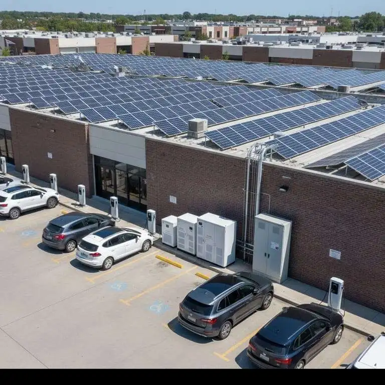
The correct placement for a voltage stabilizer in a solar+EV installation is on the AC bus, downstream of the PV inverter and upstream of the EV charging equipment. The typical single-line diagram follows this sequence:
PV Array (DC) → Solar Inverter (DC-to-AC) → AC Distribution Bus → Voltage Stabilizer → EV Charger Bank + Building Load
Why the AC side and not the DC side? Three reasons:
- Inverter output is the volatility source. The PV inverter’s AC output is where voltage fluctuations manifest. DC-side regulation would not address inverter-induced harmonics or the interaction between grid backfeed and local load.
- EV chargers require AC input regulation. Both Level 2 AC chargers and DC fast chargers (which have their own internal AC-to-DC rectifier) receive AC power from the bus. Stabilizing the AC bus protects all downstream equipment simultaneously.
- Grid interaction occurs on the AC bus. When grid power supplements solar during low-irradiance periods, or when excess solar feeds back to the grid, these bidirectional flows happen on the AC bus. The stabilizer must sit at this junction to manage both directions.
In installations with both Level 2 and DC fast chargers, a split architecture often makes sense: one stabilizer dedicated to the fast charger bank (which demands rapid response) and a separate unit for the Level 2 bank and building loads (where response time is less critical).
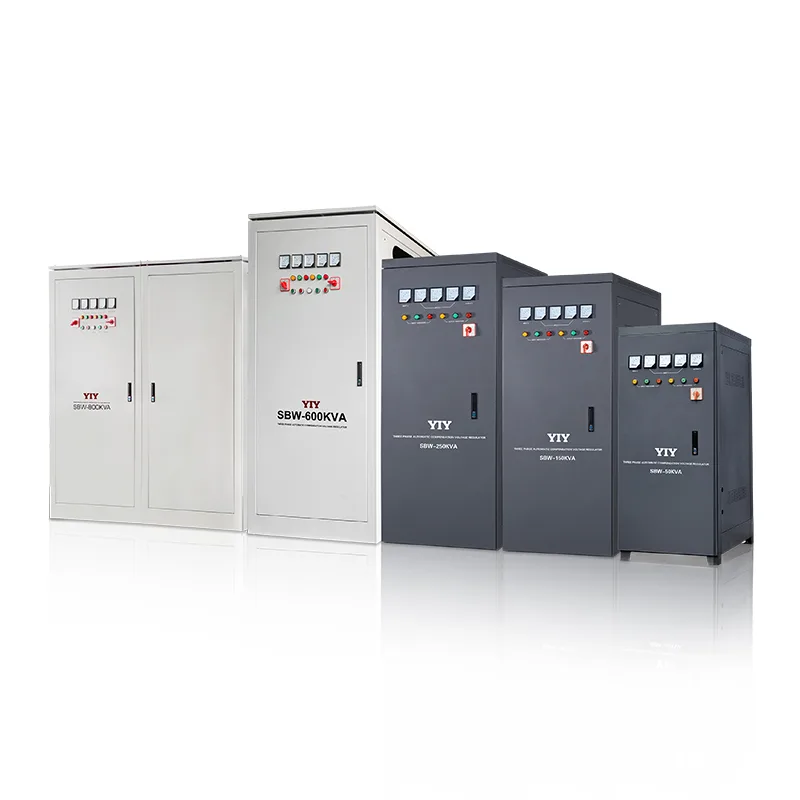
Explore our full range of EV Charger Voltage Stabilizer Solutions designed for these architectures.
Level 2 vs DC Fast Charging: Different Stabilization Needs
Level 2 and DC fast charging present fundamentally different stabilization requirements. Selecting the wrong stabilizer technology for the charger type is the most common sizing error in solar+EV projects.
Level 2 AC Charging (7-22 kW per unit)
Level 2 chargers draw moderate, relatively steady loads. A vehicle typically charges at a constant rate for 4-8 hours, with load steps occurring only at session start and end. The primary stabilization challenge is managing the aggregate effect of multiple chargers starting and stopping throughout the day.
Servo-motor stabilizers provide adequate response for Level 2 applications. Their 3-5 second correction time is acceptable because Level 2 load steps are gradual and the charger’s internal power electronics can tolerate brief voltage excursions.
Recommended products for Level 2 installations:
- PRO-3 Three-Phase Voltage Stabilizer — ideal for multi-charger commercial setups with 10-2000 KVA range
- SVC-3 Three-Phase Stabilizer — cost-effective option for parking garages with moderate charger counts
DC Fast Charging (50-350 kW per unit)
DC fast chargers are a different beast entirely. They draw massive power, cycle through charging profiles (constant current to constant voltage transitions), and generate significant harmonic distortion. Inrush currents at session start can reach 2-3 times the rated load, and the transition from one vehicle finishing to another starting creates rapid load swings of 100+ kW.
Servo stabilizers cannot respond fast enough for DC fast charger applications. The 3-5 second mechanical correction time allows voltage sags that trigger fast charger protective shutdowns, interrupting charging sessions and frustrating drivers.
IGBT-based stabilizers with electronic switching are essential for DC fast charging. Their 10-20 ms response time maintains voltage within the tight +/-3% tolerance that high-power chargers require.
Recommended products for DC fast charging:
- CVCF IGBT Voltage & Frequency Stabilizer — provides both voltage and frequency regulation, critical for off-grid or generator-backed stations
- AVC Active Voltage Conditioner — active conditioning with THD correction for high-power charging banks
Comparison: Level 2 vs DC Fast Charging Stabilization Requirements
| Parameter | Level 2 AC Charging | DC Fast Charging |
|---|---|---|
| Power per unit | 7-22 kW | 50-350 kW |
| Load step severity | Gradual (seconds) | Abrupt (milliseconds) |
| Required response time | 3-5 seconds acceptable | Under 20 ms required |
| Voltage tolerance | +/-10% | +/-3 to 5% |
| Stabilizer technology | Servo (PRO-3, SVC-3) | IGBT (CVCF, AVC) |
| Harmonic distortion | Low (<5% THD) | High (10-30% THD) |
| Frequency sensitivity | Low | High (especially off-grid) |
Capacity Sizing for Solar+EV Installations
Undersizing a stabilizer causes nuisance tripping. Oversizing wastes capital and floor space. The sizing formula for solar+EV installations must account for the unique load diversity of EV charging — not all chargers operate at full power simultaneously.
Sizing Formula:
Stabilizer KVA = (Max Simultaneous Charging Load + Building Base Load) × 1.3 Diversity Factor
The 1.3 factor provides headroom for inrush currents, PV transients, and future charger additions. The “max simultaneous charging load” is the total installed charger capacity multiplied by the simultaneous use ratio.
Simultaneous Use Ratios by Application
| Installation Type | Simultaneous Use Ratio | Rationale |
|---|---|---|
| Workplace / Office | 0.4 – 0.6 | Vehicles arrive staggered, long dwell time |
| Retail / Shopping | 0.5 – 0.7 | Moderate turnover, some overlap |
| Highway / Travel Plaza | 0.8 – 1.0 | Short sessions, high turnover, peak clustering |
| Fleet Depot | 0.7 – 0.9 | Scheduled charging, but simultaneous returns |
Example 1: Office Parking with Level 2 Chargers
Setup: 10 Level 2 chargers (7.4 kW each), 50 kW rooftop PV array, 30 kW building base load
- Total installed charging: 10 × 7.4 kW = 74 kW
- Simultaneous load (0.5 ratio): 74 × 0.5 = 37 kW
- Total load: 37 kW + 30 kW = 67 kW
- With diversity factor: 67 × 1.3 = 87 KVA
- Solution: PRO-3 100 KVA or SVC-3 100 KVA
Example 2: Highway Station with DC Fast Chargers
Setup: 4 DC fast chargers (120 kW each), 200 kW ground-mount PV array, 20 kW station auxiliary load
- Total installed charging: 4 × 120 kW = 480 kW
- Simultaneous load (0.9 ratio): 480 × 0.9 = 432 kW
- Total load: 432 kW + 20 kW = 452 kW
- With diversity factor: 452 × 1.3 = 588 KVA
- Solution: AVC 600 KVA or PWR-3 600 KVA
Why IGBT Technology Excels in Solar+EV Applications
Insulated Gate Bipolar Transistor (IGBT) based voltage stabilizers have become the standard for high-performance solar+EV installations. The technology advantages are not incremental — they represent a fundamentally different capability tier compared to traditional servo-motor designs.
Response Speed: 20 ms vs 3-5 Seconds
When a DC fast charger initiates a charging session, the load step occurs in milliseconds. A servo stabilizer, which physically moves a motor-driven contact along a transformer winding, takes 3-5 seconds to correct the resulting voltage dip. During that interval, the fast charger’s internal protection may trip, aborting the session. IGBT stabilizers switch electronically in under 20 ms — fast enough that the charger never sees the voltage excursion.
Zero Mechanical Wear
EV charging stations operate 24/7 with continuous load cycling. Servo stabilizers experience brush wear, motor fatigue, and contact degradation under these conditions, requiring maintenance every 6-12 months. IGBT units have no moving parts and maintain their performance characteristics for the full product lifespan without mechanical maintenance.
Frequency Regulation
Stations with generator backup or off-grid solar installations face frequency instability in addition to voltage fluctuation. The CVCF stabilizer accepts input frequencies from 35-70 Hz and delivers a stable 50/60 Hz output — a capability that servo stabilizers simply do not offer.
IGBT Product Lineup for Solar+EV Applications
| Product | Capacity Range | Accuracy | Response | Best Application |
|---|---|---|---|---|
| CVCF | 5-10 KVA | ±0.5% | 10 ms | Off-grid / generator-backed stations; frequency regulation (35-70 Hz input) |
| AVC | Up to 500+ KVA | ±1% | 20 ms | Large DC fast charger banks; >95% efficiency; THD correction |
| PWR-3 | 10-2000 KVA | ±1-3% | 3-5 sec | High-capacity Level 2 installations; large building loads with moderate EV charging |
Case Study: Commercial Parking Garage Solar+EV Setup
Facility Profile: A 500-space commercial parking garage in a mixed-use development with rooftop solar and comprehensive EV charging infrastructure.
Installation Specifications
- Solar array: 100 kW rooftop PV across top deck
- Level 2 chargers: 20 units at 7.4 kW each (distributed across floors 2-4)
- DC fast chargers: 4 units at 120 kW each (ground floor, dedicated stalls)
- Building base load: 45 kW (lighting, ventilation, elevators, security systems)
Load Analysis
| Load Component | Installed Capacity | Diversity Factor | Effective Load |
|---|---|---|---|
| Level 2 chargers (20 units) | 148 kW | 0.5 | 74 kW |
| DC fast chargers (4 units) | 480 kW | 0.5 | 240 kW |
| Building base load | 45 kW | 1.0 | 45 kW |
| Total | 673 kW | — | 359 kW |
Stabilizer Selection
The split-architecture approach was selected due to the different response time requirements:
- DC fast charger bank: AVC 400 KVA — provides the sub-20ms response time required for fast charger load steps, with THD correction for harmonic-rich DC charger loads. The 400 KVA rating covers the 240 kW effective load with 1.3x headroom (312 KVA required).
- Level 2 bank + building load: PRO-3 200 KVA — handles the combined 119 kW effective load (74 + 45 kW) with generous headroom for future charger additions. Servo response is adequate for the gradual load profiles of Level 2 charging.
ROI Analysis
Without stabilization, this facility experienced an average of 8 inverter shutdown events per month during peak solar+charging overlap periods. Each shutdown lasted 5-15 minutes and affected both solar production and charging revenue. The estimated annual loss:
- Lost solar production from inverter shutdowns: ~8,400 kWh/year
- Lost charging revenue from session interruptions: ~6,200 kWh/year
- Combined energy loss: ~12% of total annual throughput
- Financial impact at $0.15/kWh blended rate: ~$2,190/year
- Accelerated equipment wear (replacement cost avoidance): ~$3,500/year
- Total annual savings: ~$5,690
- Stabilizer investment payback: approximately 18 months
Frequently Asked Questions
Can solar power directly charge EVs without grid connection?
Yes, but voltage and frequency stabilization become even more critical in off-grid solar+EV configurations. Without grid reference, the PV inverter’s output frequency varies based on load conditions — it no longer has a stable 50/60 Hz grid signal to synchronize with. EV chargers require a stable frequency reference to operate correctly.
The CVCF stabilizer is designed specifically for this scenario. It accepts input frequencies from 35-70 Hz and converts them to a stable 50 Hz or 60 Hz output. This makes it the essential component for any off-grid solar charging station, island microgrid with EV charging, or installation where generator backup provides variable-frequency power.
Does the stabilizer reduce available charging power?
The power consumed by the stabilizer itself is minimal. Modern IGBT-based units like the AVC operate at greater than 95% efficiency, meaning a 100 KVA stabilizer consumes only 3-5 kW internally. This represents a 3-5% overhead — negligible when compared to the 5-15% energy losses that occur in unregulated installations due to inverter shutdowns, charger faults, and power quality-related derating.
In practice, adding a properly sized stabilizer typically increases net energy delivered to vehicles because it eliminates the interruptions and derating events that reduce throughput in unstabilized systems.
What happens during cloud transients when PV output drops suddenly?
Cloud transients are the most common trigger for voltage events in solar+EV installations. When a cloud passes over the PV array, output can drop by 60-80% in under two seconds. The stabilizer maintains output voltage by adjusting the voltage regulation ratio and, if grid-connected, by seamlessly drawing additional power from the grid to compensate.
The critical factor is response time. IGBT-based stabilizers (AVC, CVCF) respond in 10-20 ms, maintaining stable output voltage throughout the transient — the EV charger never detects the solar fluctuation. Servo-based stabilizers (PRO-3, SVC-3, PWR-3) take 3-5 seconds to reach the new setpoint, during which brief voltage dips may occur. For Level 2 chargers, this brief dip is within tolerance. For DC fast chargers, it may trigger a protection fault if the dip exceeds the +/-3% operating window.
This is why the technology selection must match the charger type: IGBT for DC fast charging, servo for Level 2 where cost optimization matters.
About YIY
Zhejiang Yiyen Holding Group Co., Ltd. (YIY) is a professional voltage stabilizer manufacturer with 16+ years of experience. With a 30,000 m² modern facility and an annual production capacity of 1,000,000+ units, our products are exported to 130+ countries. We provide OEM/ODM customization services and are ISO 9001:2015 certified.
Contact Us
Email: yiyen@yiyen.com
Phone/WhatsApp: +86 13587452904
Website: https://www.yiyavr.com/