You need to compare measured input voltage swings, motor inrush multipliers, and ambient thermal loads before finalizing a three phase servo stabilizer oil cooled.
If your distribution grid consistently dips below 340V on 400V feeders—a pattern observed across a significant portion of heavy-industrial networks—relying on nameplate ratings alone will trigger nuisance equipment trips and halt production lines. Before you issue a purchase order, this guide walks you through how servo regulation handles dynamic loads, why dielectric cooling outperforms forced air in harsh manufacturing halls, and exactly which site checkpoints you must log to size the unit correctly.
Review the complete capacity mappings in our Three-Phase Voltage Stabilizers catalog to locate the right baseline tier for your facility.
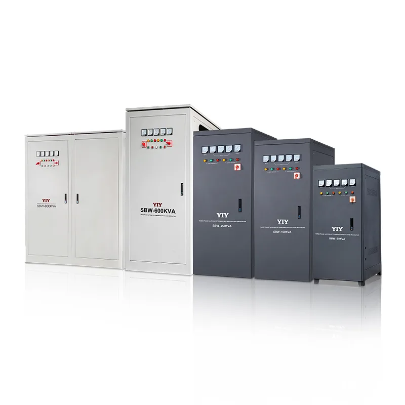
For three-phase servo projects from 150kVA upward, the YIY SBW and SBW-F cabinets are summarised on the large-capacity voltage stabilizers page.
When Do You Actually Need an Oil-Cooled Design for Continuous Industrial Loads?
You should upgrade to an oil-immersed topology whenever your facility faces chronic feeder sags, multi-phase imbalances, or 24/7 motor banks that push standard forced-air cooling past its thermal dissipation limit. If your incoming lines regularly swing beyond ±15% from nominal, sealed dielectric immersion becomes the primary factor preventing the unit from reducing its output to avoid overheating.

Submerging the autotransformer core and servo drive gear in dielectric oil transfers heat directly to the enclosure walls, allowing the regulator to sustain stable output precision during nonstop duty cycles. In practical terms, this thermal buffer means your CNC controllers and PLCs receive clean power without the processing slowdowns that typically precede a 200ms brownout.
When ambient temperatures consistently cross 45°C or conductive machining dust accumulates on the shop floor, the sealed oil bath also blocks particulate ingress that would normally clog standard ventilation fans and foul the carbon brushes.
Track these common failure symptoms to validate your site’s voltage stress before writing your specification:
* CNC spindle trips triggered by momentary feeder drops below safe operating thresholds.
* Variable frequency drive lockouts driven by phase imbalance exceeding 3% between conductors.
* Unexplained overheating in upstream distribution panels near sensitive automation gear.
Which Regulation Topology Fits Your Precision and Budget Requirements?
A servo-driven architecture solves your voltage instability by executing a continuous mechanical loop that smoothly corrects drift without injecting switching harmonics into your downstream network. You will benefit from this topology when your equipment demands stable sine wave quality rather than brute-force step corrections. Before you approve capital expenditure on a new regulator, verify that this smooth tracking aligns with your harmonic sensitivity and mixed power-factor requirements.
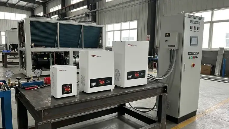
Unlike stepwise relay banks that generate loud contactor chatter during rapid corrections, the servo motor provides seamless positional adjustments that eliminate voltage stepping artifacts. Static solid-state units switch at kilohertz frequencies to arrest feeder dips, which often creates electromagnetic interference that disrupts data communication unless your cabinet shielding strictly follows IEC 61000-4-30 power quality measurement Class S standards.
In practical terms, your inductive motor banks and servo drives run without interruption even when incoming lines momentarily swing outside the ±10% safety band.
You can map your specific application against these topology baselines to confirm the optimal fit:
| Topology | Output Precision | Typical Response | Maintenance Cadence | Best Fit For |
|---|---|---|---|---|
| Electromechanical Servo | ±0.5% to ±3% | ≤1–2 seconds | Annual brush inspection & bearing check | Mixed motor loads, harmonic-sensitive automation |
| Relay Stepping | ±3% to ±6% | 0.04–0.1 seconds | Biannual contactor cleaning | Lighting banks, HVAC units, non-critical panels |
| IGBT Static | ±1% | ≤20 milliseconds | Quarterly fan filter replacement | Mission-critical lab or medical infrastructure |
If you plan to integrate the stabilizer into an existing control cabinet, carefully selecting an auxiliary relay ensures your alarm feedback and bypass circuits trigger accurately when the main servo encounters its operational limits.
What Site Measurements Determine the Correct Sizing and Installation Path?
You will select the exact model by matching your logged input range, continuous kVA demand with motor starting surges, and actual floor heat load—rather than trusting the data plate’s nominal rating alone. Before issuing an RFQ, log your feeder voltage for one full production cycle, then cross-reference those readings against the 3 phase main line stabilizer sizing framework to lock your correction window.
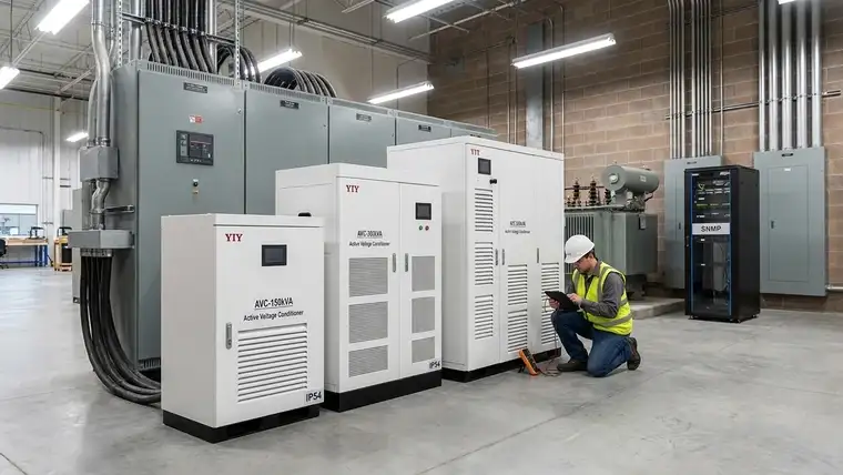
Your continuous load calculation must account for startup multipliers, where heavy inductive equipment often pulls 3 to 6 times its rated current during initial acceleration. Applying a 15% to 25% capacity safety margin above peak demand prevents the autotransformer from reaching thermal saturation during aggressive duty cycling. In practical terms, this buffer keeps your spindle motors and conveyor drives stable even when multiple machines ramp up simultaneously after a shift change.
Use this structured checkpoint table to finalize your procurement specifications:
| Check | Why it matters | If you skip it |
|---|---|---|
| Log worst-case undervoltage dips (min 340V target) | Confirms the servo’s correction range covers your grid reality | The regulator trips offline exactly when your facility needs it most |
| Verify dielectric oil reservoir access points | Ensures maintenance teams can sample fluid and replace seals safely | Routine servicing forces you to drag heavy equipment into production aisles |
| Confirm IP54 or higher cabinet rating | Protects internal windings from conductive metal dust and humidity | Dust bridging causes short circuits, voiding your manufacturer warranty |
| Specify integrated manual bypass routing | Allows downstream machinery to run directly from the grid during servicing | You lose production time every time the stabilizer requires brush replacement |
| Request copper-wound transformer specs | Lowers resistive heat generation during heavy motor inrush cycles | Aluminum alternatives overheat faster, shortening brush life and increasing long-term downtime |
Routing SNMP alarm thresholds directly into your existing PLC workflow enables predictive brush inspections instead of reactive phase faults. Aligning your cabinet design with recognized safety standards for adjustable speed drive systems becomes a straightforward operational hedge when a single 2-hour line halt easily eclipses your quarterly maintenance budget.
Frequently Asked Questions
How Should You Evaluate Pricing Across Different Three-Phase Servo Units?
Total cost should reflect winding material, inrush margins, and maintenance cycles rather than headline kVA price alone. You protect your uptime by specifying copper-wound transformers, which lower resistive heat during motor startups and extend brush service intervals. Always request a line-item breakdown confirming at least a 15% safety buffer above your peak measured load.
What Differentiates a 3-Phase Voltage Regulator from a Single-Phase Setup in Heavy Manufacturing?
A three-phase architecture balances correction across all conductors simultaneously, preventing the phase-angle drift that single-phase banks cannot address. You will avoid CNC trips and PLC faults by choosing this topology for unbalanced motor loads. Always log your actual phase-to-phase variance before ordering, as patching with single-phase units often worsens harmonic distortion.
When Should You Switch to an Oil-Cooled Enclosure Instead of Standard Air Cooling for Continuous Runs?
Oil-immersed cooling becomes necessary when ambient temperatures exceed 45°C or when conductive dust consistently fouls standard air intakes. This sealed design sustains stable dielectric strength and prevents thermal derating, ensuring steady output precision during 24/7 duty cycles. You should cross-reference your site measurements against the IEC 60038 standard voltage ratings to confirm the correction window matches your regional nominal feeders.
Which Technical Documents Do You Need from Manufacturers to Confirm Voltage Tolerance and Safety Compliance?
Required documentation must cover IEC 61000-4-11 immunity testing, a valid ISO 9001:2015 quality management certification, and recent factory acceptance test (FAT) logs. You must explicitly demand that the supplier stamps and dates the FAT voltage logs, then cross-check those baseline outputs against your own recorded feeder swings before signing the purchase contract.
Final Thoughts
Industrial operations achieve reliable power conditioning only when measured feeder swings, topology selection, and cooling methods align precisely with actual operating stressors. By mapping your real load profiles against this oil-cooled tier before procurement, you avoid thermal derating and maintain steady correction under heavy motor inrush. In high-demand environments, locking these specifications upfront directly reduces nuisance controller trips and protects critical automation uptime.
Begin with a quick-fit checklist or brief engineering consultation to validate your total load, starting current, and input-voltage window. Once those baseline parameters match your site reality, forward your internal telemetry logs to the technical desk for a finalized configuration package. You can compare before buying a voltage stabilizer using this pre-buy roadmap to ensure every dollar spent secures continuous production.