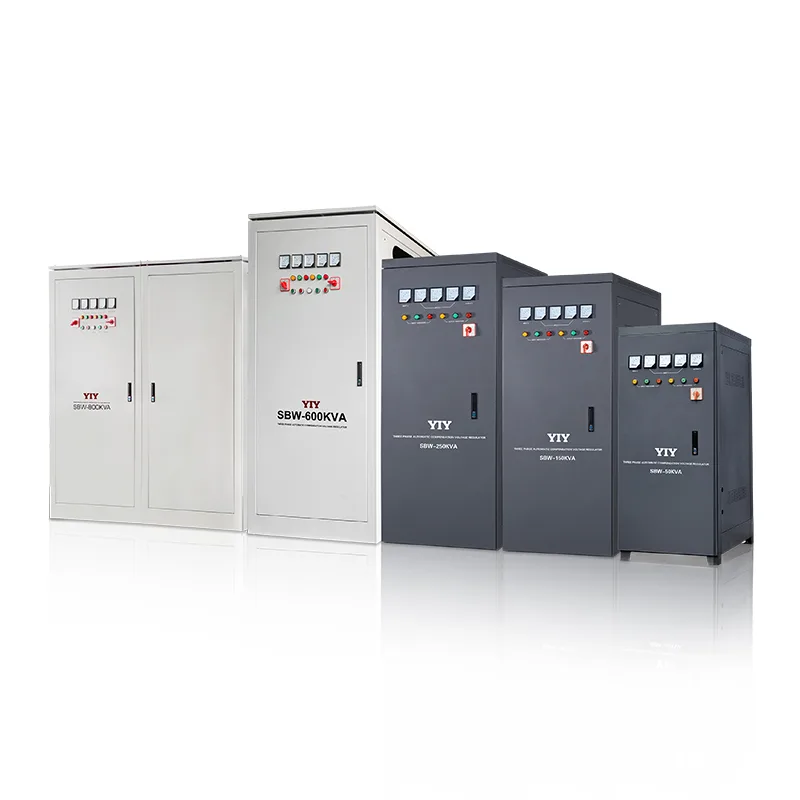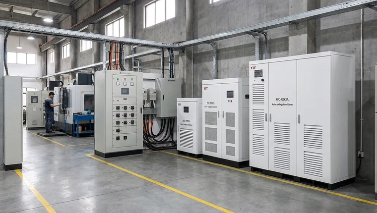
The three phase current unbalance formula is % unbalance = (maximum deviation from the average phase current ÷ average phase current) × 100, and 10% is the usual action line. The same formula is often called the current imbalance formula. Below: a worked example, the limit, and protection options.
How Do You Use the Three Phase Current Unbalance Formula?
Take one current reading per phase under normal load, average the three, find the phase furthest from that average, and divide the gap by the average. Treat the result as an early warning that tells you whether to inspect, not as a purchasing rule on its own.
Use this formula:
Current unbalance % = (maximum deviation from average phase current ÷ average phase current) × 100
For example, assume your clamp meter readings are:
- IA = 96 A
- IB = 100 A
- IC = 110 A
Average current = (96 + 100 + 110) ÷ 3 = 102 A
Maximum deviation from average = 110 - 102 = 8 A
Current unbalance = (8 ÷ 102) × 100 = 7.8%
That 7.8% result means one motor winding is carrying meaningfully different current than the others. In practical terms, you should not treat the motor as “fine” just because the total load looks acceptable. You should check voltage readings, terminals, contactors, cable impedance, motor winding condition, load coupling, and recent trip history.
| Reading to calculate | Practical formula | What it means for you |
|---|---|---|
| Average phase current | (IA + IB + IC) ÷ 3 |
Gives you the reference point for comparing all three phases. |
| Maximum current deviation | largest difference between one phase current and the average |
Shows which phase is most abnormal. |
| Current unbalance % | (maximum deviation ÷ average current) × 100 |
Converts the imbalance into a decision number you can track over time. |
| Voltage unbalance % | (maximum deviation from average line-to-line voltage ÷ average line-to-line voltage) × 100 |
Helps you identify whether incoming supply quality is driving the current problem. |
Measure AB, BC, CA voltage and IA, IB, IC current while your motor is doing real work. No-load readings can hide weak connections, voltage drop during production, poor phase distribution, or motor-start dips.
A small voltage problem turns into a much larger current problem. The U.S. DOE Motor Systems Tip Sheet #7, which draws on NEMA MG 1, puts current unbalance at 6 to 10 times the voltage unbalance. So a 2% voltage unbalance can show up as roughly 12–20% current unbalance, and a supply that looks fine on a voltmeter may already be heating the windings.
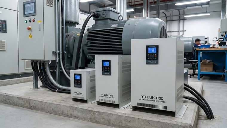
If your current imbalance follows incoming voltage imbalance, correcting supply quality with an AVR, line conditioner, or three-phase stabilizers should be considered before you keep replacing motors or resetting overloads.
What Is the Maximum Allowable Current Unbalance?
About 10%. EASA’s Tom Bishop, writing in EC&M, says that once current unbalance passes 10%, you either correct the supply to under 1% voltage unbalance or derate the motor. The DOE tip sheet sets that same 1% at the motor terminals.
| Reading | Limit | If exceeded | Source |
|---|---|---|---|
| Voltage unbalance at motor terminals | ≤1% | Derate per NEMA MG 1 Figure 20-2 | DOE Tip Sheet #7 |
| Current unbalance | ≤10% | Correct supply to below 1%, or derate | EC&M |
| Field case: 2.5% voltage unbalance, 100 hp motor | 27.7% current unbalance | Find the supply-side cause first | DOE Tip Sheet #7 |
Our view: a 10% reading caused by a weak winding isn’t a stabilizer job. When the high current follows the supply line rather than the motor lead, it’s worth working through an industrial three-phase stabilizer selection before the next rewind.
What Does Current Unbalance Do to Your Induction Motor?
You should assume sustained current unbalance is a heating and reliability problem until your measurements prove otherwise. Unequal phase current creates uneven winding stress, negative-sequence current, torque pulsation, and higher rotor heating.
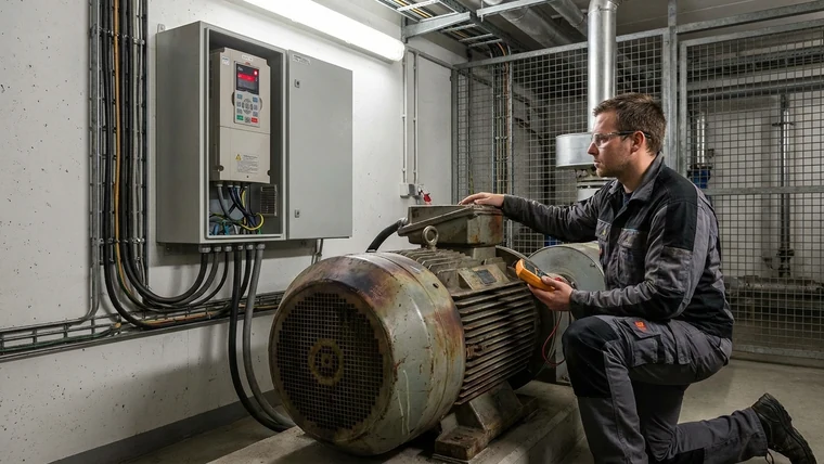
In a healthy three-phase induction motor, the supply creates a balanced rotating magnetic field. When one phase current becomes higher or lower than the others, the motor sees a negative-sequence component: a field that effectively works against the normal rotating field. That reverse component does not help your process output; it becomes heat, vibration, and stress.
| Condition | Motor effect | What it means for you |
|---|---|---|
| Current unbalance | Uneven winding current and local hot spots | One winding may age faster even when total current seems acceptable. |
| Voltage unbalance | Disproportionate current response in motor windings | A small voltage deviation can become a larger thermal issue. |
| Negative-sequence current | Reverse rotating magnetic field and torque pulsation | Your motor works against itself and wastes energy as heat. |
| Phase loss / single-phasing | Two remaining phases carry abnormal current | Your motor can overheat quickly if protection does not trip. |
| Wrong phase sequence | Reverse rotation at start | Pumps, compressors, conveyors, and fans may suffer mechanical damage. |
| Shaft voltage in induction motor systems | Bearing current risk may increase when grounding, VFDs, cable layout, and waveform distortion interact | You may need bearing grounding, insulated bearings, output filtering, or waveform diagnostics beyond a basic current check. |
These are common pathways behind three phase induction motor faults such as nuisance trips, overheated terminals, insulation breakdown, bearing problems, and repeated winding failures. The formula does not tell you the root cause by itself, but it tells you where to look.
Symptoms you should investigate include:
- one phase current consistently higher than the other two;
- one cable, fuse holder, terminal, or contactor running hotter;
- overload relay or VFD trips during peak production;
- motor frame temperature rising faster than expected;
- recurring winding failures after grid instability;
- contactor chatter during motor starts or generator transfer.
For your maintenance plan, the important point is trend behavior. A one-time abnormal reading deserves verification. A repeated pattern across shifts, starts, or peak load periods deserves a protection and supply-quality review.
Which Protection Strategy Fits Your Unbalance Pattern?
You should use layered protection: per-phase overload protection, phase-loss detection, phase-sequence verification, alarm visibility, and voltage correction when incoming supply instability is part of the problem. The formula identifies the severity; the protection layer decides whether you log, alarm, derate, trip, or correct voltage.
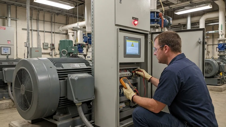
Basic overload protection is necessary, but it may not be enough when one phase is overstressed while total motor current looks acceptable. Your protection design should distinguish between a motor fault, a connection fault, a load problem, and an upstream voltage-quality issue.
| Measured condition | Protection action | What it means for you |
|---|---|---|
| Minor current deviation, stable voltage, no overheating | Continue logging current, voltage, and temperature | You have an early warning condition, not necessarily a shutdown event. |
| Rising current unbalance under load | Inspect terminals, contactors, cable lugs, load coupling, and windings | You may have a phase-specific resistance or motor condition problem. |
| High current on one or two phases with heat | Derate or stop the motor and investigate before restart | Cooling may not remove heat fast enough to protect insulation. |
| One phase lost or intermittent | Trip immediately with phase-loss protection | Single-phasing can quickly damage a running motor. |
| Wrong phase sequence after maintenance or generator work | Block start or trip with sequence protection | You prevent reverse rotation and mechanical damage. |
| Repeating voltage unbalance or dips | Add voltage stabilization and alarm/event logging | You reduce recurring stress instead of only reacting after trips. |
Use recognized voltage language when you write a specification. IEC 60038 standard voltages provides a reference for nominal system voltages. In practical terms, this helps you avoid vague RFQ language such as “normal three-phase voltage” and instead define the nominal supply your stabilizer or protection system must support.
You should also separate compliance from availability. Code-compliant protection is the baseline; high-availability production often needs more: phase-loss relay, sequence relay, per-phase current sensing, voltage monitoring, alarms, event logs, and integration with PLC or SCADA where appropriate.
Should You Choose Servo Stabilization, Relay Stabilization, or Relay-Only Protection?
For motor-heavy industrial grids with repeated voltage spread, you usually need three-phase servo stabilization plus protective relays, not relay-only protection. Relay-only devices can disconnect the motor during dangerous events, but they do not correct unstable voltage before it becomes a recurring production problem.
A servo stabilizer continuously adjusts voltage with finer control. A relay stabilizer corrects voltage in discrete steps. A protection relay monitors abnormal conditions and trips or alarms, but it does not regulate voltage. Your best choice depends on whether your main problem is correction, disconnection, or both.
| Option | Best fit | Strength | Limitation |
|---|---|---|---|
| Three-phase servo stabilizer | Motor-heavy industrial loads, weak grids, CNC, compressors, pumps, production lines | Finer voltage correction, real-time monitoring, better fit for unstable supply | Requires proper kVA sizing, inrush review, installation environment checks |
| Relay voltage stabilizer | Lighter loads, moderate voltage variation, lower sensitivity applications | Simpler architecture and suitable for less demanding conditions | Stepped correction may be too coarse for sensitive or high-availability loads |
| Phase-loss / sequence relay | Detecting lost phase, wrong sequence, or dangerous supply fault | Fast trip or alarm response | Does not correct voltage quality |
| Thermal overload relay | Sustained overcurrent protection | Essential motor protection layer | May not detect every phase-specific imbalance early enough |
| Line conditioner / filter | Noise, some transients, and power-quality cleanup | Helpful for controls in certain environments | Does not automatically solve phase loss, sequence reversal, or heavy inrush |
YIY’s three-phase servo lines are listed at ±3% output (SVC-3) and ≤2% (PRO-3), while relay designs correct in steps and hold a wider band. That narrower servo band matters when your motors, drives, PLCs, or CNC controls react to recurring voltage variation.
A relay voltage stabilizer can still be a practical fit when your load is smaller, your voltage variation is moderate, and downtime risk is limited. For harsher industrial grids, the stepped correction of relay technology may not be enough if your readings show frequent dips, wide phase spread, or high motor starting current.
The procurement mistake to avoid is specifying only “380 V / 400 V / 415 V three phase” without measured input range, phase spread, inrush current, duty cycle, ambient heat, dust, humidity, and trip history. A stabilizer can look correct on paper and still fail during motor starts if it was sized from nominal values only.
What Should You Check Before Sizing a Stabilizer?
You should size the stabilizer from measured site behavior, not from the motor nameplate alone. Your nameplate tells you the rated load, but your logs tell you what the supply and load actually do during production.
Use this decision structure before you finalize equipment:
| Check | Why it matters | If you skip it |
|---|---|---|
| Measured input voltage range on all phases | Shows real grid instability and phase spread | You may choose too narrow a correction range. |
| Total kVA and power factor | Converts your load into stabilizer capacity | You may overload the stabilizer during normal operation. |
| Motor starting / inrush current | Motors can demand several times running current at start | You may get nuisance trips or voltage sag at startup. |
| Load mix and duty cycle | Pumps, compressors, welders, CNC machines, and controls behave differently | You may choose the wrong topology or protection package. |
| Phase-loss and sequence risk | Protects against burnout and reverse rotation | A wiring or supply fault may become mechanical damage. |
| Ambient temperature, dust, humidity, ventilation | Affects enclosure, cooling, IP rating, and service life | Components may age faster or trip under heat. |
| Alarm and event logging requirements | Helps maintenance teams prove what happened | You lose diagnostic evidence after trips. |
| Generator or transformer transfer behavior | Frequency and voltage may shift during changeover | Your settings may not match backup-power operation. |
For a deeper execution step, use measured phase current, voltage range, inrush behavior, and load mix as inputs for 3 phase main line stabilizer sizing. If you are still comparing technologies, your broader industrial voltage stabilizer selection process should include input range, total kVA, power factor, startup current, site environment, and required protection functions.
Technical standards can help you describe supply disturbances clearly. For voltage dips and interruptions, IEC 61000-4-11 voltage dip and interruption immunity testing provides recognized terminology. In practical terms, that helps you explain whether your problem is a short dip, a repeated interruption, or a broader unstable-supply pattern.
When Should You Log Site Data Before Buying Equipment?
You should log site data before procurement whenever current unbalance changes by shift, generator mode, production line, or motor start sequence. A single calculation is useful, but a moving result usually means your site condition is dynamic.
Follow this workflow before you lock the specification:
- Measure line-to-line voltage: record AB, BC, and CA under real operating load.
- Log line current: record IA, IB, and IC during normal production, low load, and peak demand.
- Record frequency: pay special attention during utility-to-generator transfer.
- Tag load status: note which motor, pump, compressor, welder, CNC group, or production line is running.
- Capture motor start events: record inrush periods, voltage dips, and contactor chatter.
- Review trip history: collect overload relay records, VFD alarms, PLC events, and maintenance notes.
- Verify phase sequence: check after commissioning, transformer work, generator work, or cable changes.
- Review phase-loss response: have qualified personnel confirm that the protection scheme trips or alarms as intended.
Your review package should include 24–72 hours of voltage/current logs, one-line diagram, motor list with kW or kVA, starting method, generator details, alarm history, ambient temperature, enclosure location, dust and humidity notes, and panel or nameplate photos.
This step protects you from undersizing. It also helps you decide whether your issue is best solved by tightening terminals, replacing contactors, correcting load imbalance, adding phase-loss protection, or installing a three-phase stabilizer with wider input tolerance and better monitoring.
Frequently Asked Questions
How Does a 2% Voltage Unbalance Translate to Motor Current Stress?
Apply the DOE multiplier: 2% on the voltage side points to something like 12–20% on the current side, well past the 10% action line. Confirm it on site by checking whether the highest-current phase lines up with the lowest-voltage phase during production.
Can a Voltage Stabilizer Correct Current Unbalance Directly?
A voltage stabilizer does not directly control motor current. It corrects unstable or unequal supply voltage, which can reduce current unbalance caused by poor incoming power. If current remains uneven after voltage correction, you should inspect terminals, contactors, cable impedance, winding condition, load coupling, grounding, and motor bearings.
What Should You Know About Single Phase Motor Overload Protection?
Single phase motor overload protection protects a single-phase motor from sustained overcurrent and overheating. You should match it to motor full-load current, service factor, ambient temperature, starter setting, and duty cycle. As a concrete check, compare the overload relay range with the motor nameplate current before commissioning.
What Is the Difference Between Single-Phase Motor Overload Protection and Single-Phasing Relay Protection?
Single-phase motor overload protection protects a single-phase motor from overheating. Single-phasing relay protection detects a lost phase in a three-phase supply. They are not interchangeable. For a three-phase motor, you should verify that each phase has appropriate overload protection and that the phase-loss relay trips or alarms during a controlled test by qualified personnel.
Should You Choose Servo or Relay Stabilization for a Highly Unbalanced Industrial Grid?
For a highly unbalanced industrial grid, you should normally evaluate a three-phase servo stabilizer first because it offers finer correction and better suitability for motor-heavy loads. A relay stabilizer may still fit lighter loads with moderate voltage variation, but you should confirm this with voltage logs, inrush data, and downtime risk.
Final Thoughts
You should treat the three-phase current unbalance formula as a diagnostic trigger that leads to better protection decisions. The calculation helps you identify imbalance, but your next step should connect that number to voltage readings, phase-loss risk, motor condition, site environment, and stabilizer sizing.
Your practical sequence is simple: calculate current deviation, compare it with voltage unbalance, inspect phase-specific connection and load issues, verify overload and phase-loss protection, then decide whether supply-side correction is needed. If the imbalance follows incoming voltage instability, the right question is not only “What is the nominal voltage?” but “What does your site actually deliver under load?”
Before procurement, compare before buying a voltage stabilizer by checking logs, correction precision, protection features, inrush behavior, environment, and downtime risk. For a low-friction next step, start with a quick-fit checklist or first-pass specification review. If the case looks sensitive, share your logs, motor list, starting method, and site conditions for an engineering review.