Choose troubleshooting a servo 150 power feed before replacing parts when your servo-driven machine shows repeated undervoltage alarms, unstable feed movement, delayed drive faults, wiring uncertainty, or voltage fluctuation that may come from the supply side rather than the motor or drive alone.
You can save confusion by treating the problem as a diagnostic and selection decision: first prove whether the fault is wiring, grounding, motor insulation, PLC interface, drive behavior, or incoming voltage quality; then decide whether a servo, relay, or IGBT voltage stabilizer is the right protection method.
This guide will help you answer when troubleshooting is necessary, what to measure, how servo correction compares with other topologies, how to size the protection, and what to verify before you request a quote.
When Does Troubleshooting a Servo 150 Power Feed Make Sense?
You should use this diagnostic path when repeated servo faults coincide with unstable voltage, wiring problems, ground faults, or unclear alarm timing. If your CNC axis, robotics line, packaging machine, or industrial power-feed system keeps faulting after reset, you need evidence before you replace a motor, drive, PLC card, or control board.
A structured check is especially useful when you see:
- Immediate servo drive alarm after power-up.
- Delayed alarm after the axis starts moving.
- Erratic feed rate, vibration, position drift, or unstable servo power assist behavior.
- Repeated undervoltage, overvoltage, blown fuse, or DC bus alarms.
- Heat, dust, humidity, coolant exposure, or corrosion inside the cabinet.
- A servo motor with gear reducer that fails under load but looks normal at idle.
- A servo drive connection with PLC where the fault may involve shielding, grounding, interlock wiring, or signal noise.
Your first safety boundary is simple: disconnect power, follow lockout practices, and confirm stored energy is discharged before insulation, winding, or continuity testing. For machinery electrical work, IEC 60204-1 machinery electrical equipment safety requirements give a recognized reference point for safe electrical design and maintenance practices. Practically, this means your diagnostic workflow should protect people first, then protect the machine.
Do not use hobby references such as 3 wire servo wiring, BEC servo wiring, or Futaba servo wiring diagrams as substitutes for industrial servo drive documentation. Those diagrams may help you understand small servo signal conventions, but they do not replace your OEM drive manual, machine safety schematic, PLC I/O drawing, or cabinet wiring schedule.

How Does Servo-Based Voltage Correction Work?
You should think of a servo voltage corrector as a continuous electromechanical regulator that adjusts output voltage through controlled brush movement rather than step switching. In a typical industrial unit, the correction chain is:
input sensing → MCU/control board → servo motor → carbon brush movement on autotransformer → corrected output voltage
That sequence matters because it explains both the strength and limitation of servo technology. A servo voltage stabilizer is usually a good fit when your load needs smoother output regulation than relay switching can provide, but your application does not require the near-instant correction of a fully static system.
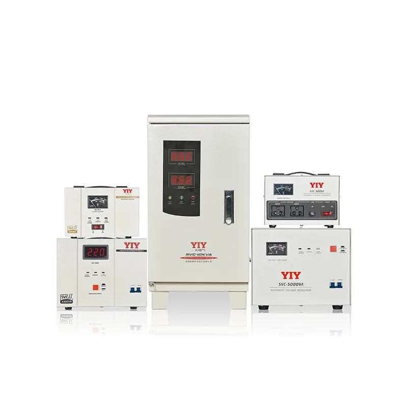
YIY servo stabilizers use MCU-controlled servo motors to drive carbon brushes across an autotransformer for continuous voltage regulation. Typical model-dependent performance is ±0.5–3% output precision and ≤1–2s response. For you, the practical meaning is straightforward: servo correction can help stabilize drifting input voltage for sensitive drives, CNC controls, servo feeders, and industrial machines, but it is not meant to eliminate every fast transient or every non-power-related servo fault.
Which Technology Fits Your Fault Pattern: Servo, Relay, or IGBT?
Servo usually fits you when voltage fluctuates over time and your industrial load needs accurate, smooth correction without moving to a higher-cost static system. Relay can fit simpler cost-driven loads, while IGBT is better when your process is sensitive to fast disturbances and needs electronic correction speed.
| Technology | How it corrects voltage | Practical fit for your load | Main caution |
|---|---|---|---|
| Servo | Motor-driven carbon brush adjustment on autotransformer | CNC, servo feeders, packaging lines, industrial motor loads, mixed production equipment | Requires periodic carbon brush and mechanical inspection |
| Relay | Tap switching through relays | Basic loads, less sensitive equipment, lower-budget protection | Step changes may not suit sensitive servo drives |
| IGBT/static | Fast electronic correction | Critical automation, medical equipment, fast disturbance environments | Higher specification and cost expectations |
For your selection, match the topology to the fault pattern:
- If voltage slowly rises and falls during shifts, servo correction may be enough.
- If the load is basic and occasional tap changes are acceptable, relay may be adequate.
- If fast voltage sags, sensitive electronics, or critical uptime dominate the decision, an IGBT voltage stabilizer may deserve review.
- If the fault follows a motion cycle, deceleration, encoder cable, or PLC signal event, voltage correction alone may not solve it.
Nominal voltage also matters when your equipment is exported or installed across different grid systems. Use IEC 60038 standard voltages as a reference when you define whether your site expects 230 V, 400 V, 415 V, 480 V, or another nominal system. In practical terms, you avoid specifying a unit that looks correct on paper but does not match the customer’s real supply.
What Are the 7 Checks Before You Replace Parts?
You should complete these seven checks before you replace the servo motor, drive, PLC module, or voltage protection device. The goal is to prove the failure path instead of swapping expensive components based on symptoms.
| Check | Why it matters | If you skip it |
|---|---|---|
| 1. Isolate power and verify safe access | You protect personnel before meter work, cabinet inspection, or insulation testing. | Shock, arc flash, or accidental equipment damage can occur. |
| 2. Inspect terminals, plugs, pinout, and corrosion | Loose terminals and oxidized contacts can mimic intermittent drive faults. | You may replace a good drive while the real fault remains. |
| 3. Measure incoming voltage under load | Servo faults often appear only during acceleration, cutting, pressing, or line startup. | Idle voltage may look normal while operating voltage collapses. |
| 4. Check grounding and shield bonding | Poor grounding can inject noise into encoder wiring, PLC signals, and drive feedback. | Position errors may be misdiagnosed as motor or controller failure. |
| 5. Compare alarm timing | Immediate alarm at power-up suggests input, drive, DC bus, or protection issues; delayed alarm after motion suggests motor, cable, load, or insulation behavior. | Your first replacement target may be wrong. |
| 6. Test windings and insulation | T1/T2/T3-to-ground testing helps identify leakage, moisture, or insulation breakdown. | A damaged motor cable or winding fault may be missed. |
| 7. Confirm stabilizer output at no-load and operating load | A regulator may look stable at idle but fail during real machine cycles. | Undervoltage trips and feed instability may continue after installation. |
A commonly cited servo motor troubleshooting range treats 600–2000 MΩ phase-to-ground insulation resistance as normal during megohmmeter checks. In practical terms, a high reading suggests the winding is not leaking current to ground, while a very low reading can indicate moisture, insulation damage, or a short path that needs repair before you blame the supply.
How Should You Size Voltage Protection for a Servo Power Feed?
You should size the protection from measured load behavior, not from nameplate kVA alone. Servo-driven equipment can draw higher current during acceleration, behave differently during deceleration, and create nuisance faults when the stabilizer is undersized for real operating cycles.
Start with these inputs:
| Specification input | What to collect | What it means for you |
|---|---|---|
| Phase type | Single-phase or three-phase supply | The stabilizer must match your distribution and machine feeder. |
| Nominal voltage | Site voltage and allowable variation | Your unit must correct the real voltage window, not only the rated value. |
| Running current | Current during steady operation | This sets the baseline load requirement. |
| Acceleration current | Current during startup or axis movement | This helps prevent trips during the moments your machine stresses the supply. |
| Regenerative behavior | Deceleration events, braking units, DC bus alarms | This prevents you from treating every deceleration alarm as a supply fault. |
| Output tolerance | Required voltage accuracy for drives and PLC panels | Tighter tolerance may support more stable servo operation. |
| Environment | Dust, heat, humidity, cabinet airflow, IP needs | Harsh sites may need filtered ventilation, cabinet cooling, or higher protection. |
| Bypass and service access | Manual bypass, terminal access, brush access, spares | Maintenance becomes planned work rather than emergency downtime. |
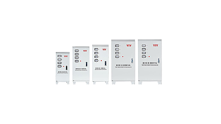
For industrial procurement, use an industrial voltage stabilizer selection process before RFQ so your quote includes kVA, phase, input range, output accuracy, bypass, protection, monitoring, and enclosure requirements. If your supply is three-phase or protects a main feeder, a separate 3 phase main line stabilizer sizing review can help you avoid undersizing the unit for distribution-level load behavior.
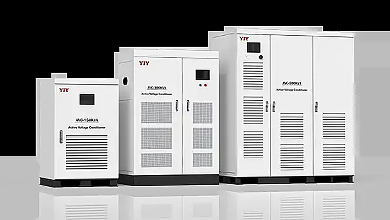
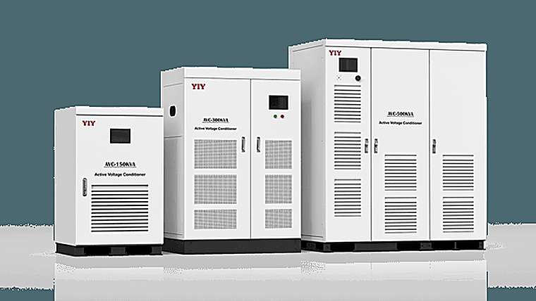
YIY’s stabilizer portfolio covers 0.5KVA–3000KVA and supports servo, relay, and IGBT technologies. Treat that range as capability context, not an automatic sizing answer. Your correct rating still depends on measured current, duty cycle, voltage fluctuation, load mix, and future expansion.
What Should Your Procurement Checklist Include?
You should compare suppliers using the same specification sheet, otherwise the lowest quote may simply exclude the features your application needs. For a servo motor operated line voltage corrector, price is usually affected by kVA rating, phase configuration, input range, output tolerance, cabinet design, copper/aluminum choice, IP rating, bypass, surge protection, alarms, monitoring, and customization.
| Check | Why it matters | If you skip it |
|---|---|---|
| Same kVA and phase rating | Ensures all suppliers quote the same electrical class. | A cheaper quote may be undersized. |
| Input range and output accuracy | Confirms the unit can correct your real voltage swing. | Undervoltage or overvoltage alarms may continue. |
| Protection functions | Overload, short-circuit, delay, surge, over/under-voltage protection reduce risk. | One abnormal event can damage drives or controls. |
| Bypass design | Allows service without unnecessary shutdown where suitable. | Maintenance may require full production interruption. |
| Monitoring and alarms | Helps your maintenance staff diagnose repeat events. | You lose evidence when faults return. |
| Cabinet and environment rating | Dust, heat, humidity, and ventilation affect service life. | Carbon brushes, terminals, and cooling paths degrade faster. |
| Quality documentation | Factory test records and process controls support procurement confidence. | You may not know whether the quoted unit was tested consistently. |
| Spare parts and service terms | Brushes, boards, meters, and support access affect lifecycle cost. | A small repair can become a long stoppage. |
Supplier quality systems are also worth checking. ISO 9001:2015 quality management requirements provide a recognized framework for process control. For you, that does not guarantee the exact model is right, but it gives procurement a concrete way to verify manufacturing discipline.
When you compare total cost, include downtime risk rather than only the servo motor operated line voltage corrector price. A lower base unit cost can be less attractive if it excludes bypass, monitoring, surge protection, adequate enclosure design, or spare-part support.
How Do You Decide After the Measurements?
You should choose the solution only after your fault pattern and measurements point to a clear cause. If your voltage logs show unstable incoming supply during fault events, voltage stabilization becomes a serious option. If insulation resistance is low, grounding is poor, or the fault follows a cable bend or encoder signal, repair work should come first.
Use this decision structure:
| Your finding | Likely direction | Practical next step |
|---|---|---|
| Voltage drops during acceleration or high machine load | Supply-side or feeder issue | Size a stabilizer from measured load and voltage window. |
| Immediate alarm at power-up | Drive, DC bus, input, or protection issue | Verify incoming voltage, drive health, fuses, DC bus, and wiring. |
| Delayed alarm after motion starts | Motor, cable, encoder, load, or insulation issue | Test cable, windings, grounding, encoder feedback, and mechanical load. |
| Stable voltage but erratic positioning | Control, feedback, grounding, or mechanics | Review PLC wiring, shield bonding, encoder cable, and mechanical backlash. |
| Repeated faults across multiple machines | Site power quality or distribution issue | Review main feeder voltage, phase balance, and stabilizer topology. |
| Fault only on one axis | Local motor, cable, drive, or load issue | Compare against a known-good axis before replacing parts. |
If your decision is moving toward purchase, use a final buyer comparison such as compare before buying a voltage stabilizer to align downtime risk, capacity, input range, protection features, and quotation scope before you commit.
Frequently Asked Questions
What Field Data Makes a Supplier Review Faster?
Send a short evidence pack: utility reading at the panel, feeder rating, machine model, alarm code, phase count, cabinet photos, and a note showing exactly when the trip appears. This lets the engineering team filter site-power risk from local machine defects.
Which Symptom Suggests a Facility-Level Issue?
Look for repeat trips on several machines, complaints during peak utility hours, or alarms that arrive when compressors, welders, pumps, or other heavy loads start. A problem limited to one axis or one cable normally needs local service work first.
Why Should Dynamic Load Behavior Be Recorded?
A production line does not consume electricity evenly. Short peaks during motion can be more important than the steady nameplate value, so recording the busy part of the cycle prevents an undersized protection choice.
How Can Buyers Keep Quotes Comparable?
Use one checklist for every offer: rating, phase, correction window, accuracy, bypass, cabinet grade, surge package, alarms, warranty, spares, and test documents. If one offer removes any item, treat the lower price as a different scope.
What Details Help YIY Choose Between Regulator Types?
Share the site range, load current, duty cycle, required tolerance, environment, and fault notes. YIY can then match the job to smooth electromechanical correction, economy tap switching, or faster static regulation.
Final Decision: Diagnose First, Then Choose the Right Topology
You should treat troubleshooting as the low-risk first step before you buy or replace. A servo stabilizer may fit your application when voltage drift affects industrial servo loads and you need smooth, accurate correction. Relay may fit simpler cost-sensitive protection. IGBT may fit faster critical-power correction.
Your next step can be simple: prepare a first-pass evidence pack with machine type, voltage readings, phase type, load current, fault timing, cabinet photos, and the current protection setup. YIY can review that information with you and help confirm whether servo, relay, or IGBT is the best fit for your application and maintenance context—before you spend budget on the wrong replacement.