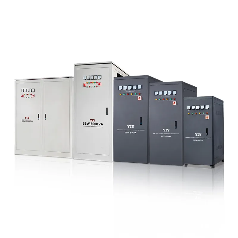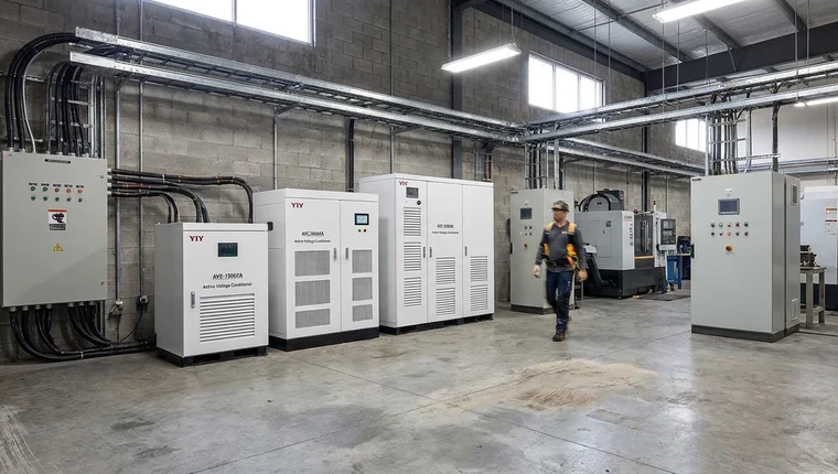
Before buying a servo stabilizer 3 phase, compare your measured load profile, input-voltage window, phase balance, output accuracy, response time, bypass design, protection functions, installation conditions, maintenance needs, and supplier sizing support before you shortlist any model.
This guide will help you decide what problem the stabilizer must solve, when servo technology fits better than relay, static, or IGBT regulation, how the correction loop works, which 15 RFQ checks to complete, and what verification actions you should take before procurement approval.
A typical three-phase servo AVR regulates output within ±0.5% to ±3% in about 1–2 seconds, while nominal voltage assumptions should align with IEC 60038 standard voltage definitions. For you, that means a servo AVR is often a practical industrial voltage stabilizer when your site has sustained voltage swings, but it should still be sized from real field measurements rather than nameplate voltage alone.
What Problem Is a Three-Phase Servo Stabilizer Actually Solving?
You are trying to keep industrial equipment inside a safe voltage window when the grid, transformer, feeder, or load behavior causes unstable voltage. A three-phase servo stabilizer is designed to correct undervoltage, overvoltage, load-driven voltage drops, and phase-related voltage instability before these problems become nuisance trips, overheated motors, rejected output, or avoidable downtime.

If you are a plant engineer, panel builder, EPC contractor, or procurement stakeholder, your comparison is usually not theoretical. You may be protecting CNC machines, production lines, pumps, compressors, elevators, textile machinery, packaging equipment, or mixed three-phase panels where one unstable feeder can interrupt several downstream processes.
Nominal voltage is only the starting point. A “380 V” or “400 V” system can require very different correction capacity depending on how low the voltage falls during peak production, motor starting, generator transfer, or weak-grid periods. Before shortlisting three-phase stabilizers, collect measured input voltage, load kVA, starting current, and phase behavior so your RFQ reflects the site instead of an ideal electrical drawing.
| Input to measure | Why it matters in practice |
|---|---|
| Minimum / maximum input voltage | Defines the correction range your AVR must handle without dropping out |
| Load kVA / kW and power factor | Prevents undersizing when apparent power is higher than real power |
| Starting current | Motors, compressors, lifts, and pumps can demand several times running current |
| Phase behavior | Reveals unbalance, weak phases, or single-phasing risk before equipment trips |
| Installation environment | Heat, dust, humidity, altitude, and ventilation affect long-term reliability |
Poor voltage quality has a business cost even when it does not cause immediate failure. It can trigger contactors, increase motor heat, shorten component life, and create intermittent production faults that look like machine problems rather than power problems. For your procurement process, the important shift is to specify a stabilizer around operating evidence, not only around a catalogue kVA rating.
Phase unbalance and single-phasing deserve separate attention. A stabilizer can regulate voltage, while motor protection relays detect abnormal phase loss, overload, or severe unbalance and disconnect the motor. Treat these as complementary protections, not substitutes.
When Should You Choose Servo Instead of Relay, Static, or IGBT Regulation?
You should usually choose servo regulation for general industrial three-phase loads when you need a practical balance of capacity, voltage accuracy, purchase cost, and long-term serviceability, not the fastest possible correction. Servo stabilizers remain a mainstream fit for heavy machinery, standard production equipment, pumps, compressors, CNC support loads, and broad three-phase distribution where ±0.5% to ±3% output regulation and about 1–2 seconds correction are acceptable in practice.
| Topology | Response behavior | Typical accuracy / control | Maintenance profile | Cost profile | Best application fit |
|---|---|---|---|---|---|
| Relay stabilizer | Step correction; less smooth | Wider voltage steps | Low complexity, relay wear over time | Lowest | Simple, low-cost loads with modest sensitivity |
| Servo AVR | Continuous motor-driven correction | Commonly ±0.5%–±3% | Brush, motor, and contact inspection needed | Moderate | Industrial machinery, production lines, mixed three-phase loads |
| Static stabilizer | Faster electronic correction | Tighter and smoother than relay in many designs | Fewer moving parts, more electronic diagnostics | Higher | Loads affected by frequent or fast voltage swings |
| IGBT / digital stabilizer | Very fast electronic or conversion-based regulation | Tight power-quality control, depending on design | Electronics-focused service and module support | Highest | Critical loads, medical, lab, precision automation, demanding PQ environments |
The practical takeaway is straightforward. A relay unit may protect basic equipment, but its stepped output can be too coarse for more sensitive industrial loads. Static or IGBT voltage stabilizer designs can be better when your process cannot tolerate fast dips, flicker, or tight power-quality deviations.
Servo becomes the engineering middle ground when downtime risk matters but double-conversion cost is hard to justify. If one unstable feeder can stop multiple machines, the lower upfront cost of a relay unit may be offset by nuisance trips, troubleshooting time, and avoidable production interruption.
For indoor and standard industrial facility selection, focus on measured voltage range, kVA, starting current, phase balance, ventilation, dust level, humidity, and enclosure protection. Some suppliers emphasize outdoor or extreme-environment systems; your decision logic may be different if the stabilizer will sit in a controlled electrical room, workshop, or standard industrial panel. In that case, custom IP rating, filtering, or cooling should be specified only when your site conditions require it.
For modern maintenance workflows, also compare alarm visibility, event logs, bypass status, and whether the AVR can integrate with your plant control or maintenance process. Voltage dip and interruption behavior is commonly evaluated under standards such as IEC 61000-4-11 voltage dip and interruption immunity testing, which helps you discuss power disturbances in a shared engineering language rather than using vague descriptions such as “unstable grid.”
How Does the Servo Motor and Autotransformer Correction Method Work?
You are selecting a closed-loop voltage correction system, not just a fixed-ratio transformer. A three-phase servo AVR senses your output voltage, compares it with a set value, then uses an MCU-controlled servo motor to move a carbon brush on an autotransformer so the turns ratio changes and the output voltage returns to the target level.
The correction loop usually follows this sequence:
- Voltage sensing: The control board samples each phase output voltage and checks whether it is above or below the set value.
- MCU comparison: The controller compares measured voltage against the reference voltage, such as 380 V or 400 V depending on your system.
- Servo command: If voltage is outside the allowed band, the MCU drives the servo motor clockwise or counterclockwise.
- Brush movement: The servo motor moves the carbon brush along the autotransformer winding to adjust the effective turns ratio.
- Output stabilization: The corrected voltage is delivered to your load until the controller detects a new deviation.
- Protection response: If the condition exceeds the safe correction range, protection functions such as overvoltage, undervoltage, overload, phase loss, or bypass indication should act or alarm.
Typical servo stabilizers regulate output within ±0.5% to ±3% and correct many voltage deviations within ≤1–2 seconds. In practical terms, ±0.5% to ±3% tells you how tightly the unit can hold voltage for equipment tolerance, while ≤1–2 seconds is suitable for many industrial grid fluctuations but not every ultra-fast transient, switching spike, or micro-interruption.
This distinction matters during procurement. A servo voltage stabilizer, automatic voltage regulator, or line conditioner stabilizes sustained voltage variation. It is not a full substitute for surge protection, harmonic filtering, UPS backup, or motor overload protection. If your site has lightning exposure, high THD, frequent blackouts, or motor thermal risk, specify complementary SPD, filters, UPS, or motor protection relays instead of expecting one AVR to solve every power-quality issue.
For your maintenance team, ask for observability as well as regulation accuracy. Useful options include voltage/current display, alarm visibility, event logs, phase loss indication, overload status, bypass position, and optional remote monitoring for PLC, BMS, or maintenance systems.
Which 15 Specifications Should You Compare Before Sending an RFQ?
Your RFQ should be based on measured site data and real load behavior, not only the equipment nameplate. Correct selection starts from load, power factor, starting current, safety margin, input voltage range, phase type, application sensitivity, and installation conditions.
For sizing, treat kVA as an engineering result: kVA ≈ kW ÷ power factor, then adjust for simultaneous demand, motor inrush, and future expansion. In practice, this means a “15 kW” load may not fit a 15 kVA unit if the power factor is low, the load is nonlinear, or several motors start together.
| Check | Why it matters | If you skip it |
|---|---|---|
| 1. Total connected load | Shows the maximum equipment that could be powered | You may undersize the stabilizer before production expands |
| 2. Simultaneous operating load | Reflects real demand, not the full nameplate sum | You may overpay or still miss peak operating conditions |
| 3. Motor starting current / inrush | Motors, compressors, lifts, and pumps can draw several times running current | Voltage may sag during startup and trip downstream equipment |
| 4. Power factor | Converts kW into apparent power demand in kVA | A kW-only RFQ can select the wrong capacity |
| 5. Safety margin and future expansion | Gives room for aging, added machines, and peak demand | Your unit may run hot or overloaded after minor line changes |
| 6. Input voltage range | Defines how low/high the grid can go before correction fails | The AVR may drop out during the exact fluctuation you bought it for |
| 7. Output voltage requirement and accuracy | CNC, PLC, and test equipment may need tighter regulation than motors | Sensitive loads may still fault despite “stable” voltage |
| 8. Response time | Servo units commonly correct sustained fluctuations in seconds, not microseconds | Fast dips or transients may still need UPS, SPD, or static regulation |
| 9. Phase type and phase balance | Three-phase loads need stable line-to-line voltage and phase health | Phase loss or severe imbalance can damage motors |
| 10. Protection functions | Check over/under-voltage, overload, short-circuit, phase loss, delay, and alarm | Faults become harder to isolate and riskier to operate through |
| 11. Bypass type | Manual or maintenance bypass affects service continuity | Inspection may require shutting down protected loads |
| 12. Cooling and ventilation | Airflow controls transformer and brush temperature | Heat buildup shortens component life |
| 13. Enclosure, IP rating, and cable entry | Dust, humidity, cable size, and panel layout affect installation fit | Site modifications can delay commissioning |
| 14. Installation clearance and access | Space is needed for airflow, access, and safe maintenance | Technicians may not be able to inspect or tighten terminals |
| 15. Ambient conditions and monitoring | Temperature, humidity, dust, altitude, alarms, and logs affect operation and troubleshooting | Standard indoor designs may need filters, heaters, derating, or better diagnostics |
Application sensitivity should drive the final specification. A three-phase servo voltage stabilizer for CNC machines may justify tighter correction accuracy and better alarm visibility, while an industrial automatic voltage regulator for motor loads should emphasize inrush tolerance, overload protection, ventilation, and phase-loss protection.
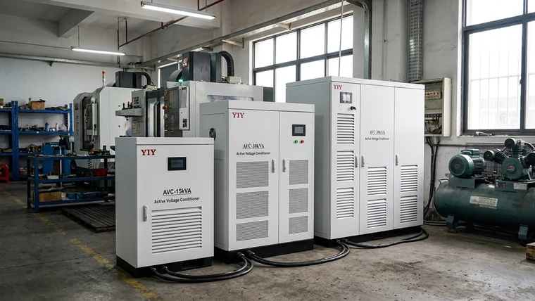
Capacity labels also need context. A servo stabilizer 15kVA 3 phase may be suitable for a small mixed-load panel, but only if your measured simultaneous kVA, starting current, power factor, and expansion margin fit within the unit’s thermal and correction limits.
If you are converting load records into a specification, use 3 phase main line stabilizer sizing logic to organize your load list, input-voltage range, operating schedule, and bypass needs before final RFQ release. For broader site-level decisions, your industrial voltage stabilizer selection review should also include upstream feeder behavior, protected-load sensitivity, and maintenance access.
Before issuing the RFQ, add maintenance expectations: carbon brush wear inspection, ventilation cleaning, terminal tightening, alarm checks, and planned inspection intervals based on manufacturer guidance and duty cycle. The cost of skipping this step is not just service expense; an avoidable stabilizer fault can stop the same production line it was purchased to protect.
What Final Procurement Checks Should You Complete?
You should finish procurement by verifying phase protection, single-phasing risk, allowable unbalance limits, site conditions, and the complete sizing data package before approving the three-phase servo stabilizer RFQ. This acceptance review helps you catch specification gaps before they become commissioning delays or fault disputes.
Does the Stabilizer Alone Handle Phase Unbalance Protection?
No—treat the stabilizer and motor protection relay as complementary devices. The AVR regulates voltage, while a motor protection relay should detect phase loss, severe voltage/current unbalance, overload, and phase sequence faults and trip the motor when needed.
Your verification action: ask the supplier to mark which protections are inside the stabilizer and which must remain in your MCC or motor control panel. Then compare that answer against your motor relay settings and protection drawings.
How Does an Unbalanced Three-Phase System Affect Motors and Production Equipment?
Unbalance can make motors run hotter, reduce torque quality, and increase nuisance trips in drives, compressors, pumps, and CNC support systems. In practice, one weak phase can overload motor windings even when average line voltage looks acceptable.
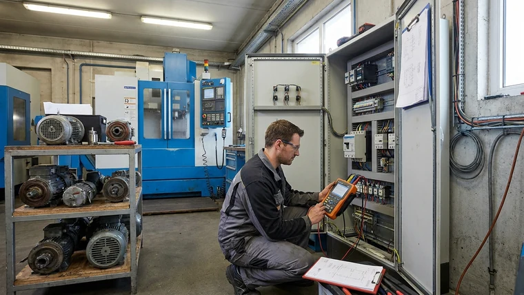
Your verification action: check logged line-to-line voltage, phase current, and trip history together. Standards such as IEC 60034-26 guidance on effects of unbalanced voltages on three-phase motors can support the engineering discussion, but your final settings should still reflect your actual motor manuals, relay guides, and operating conditions.
What Should You Check for Single-Phasing Risk Before Buying?
Check whether your incoming feeder, contactors, fuses, breakers, and upstream distribution have a history of blown fuse links, loose terminals, or one-phase voltage collapse. Ask for phase-loss detection, alarm indication, and trip logic in the stabilizer or external protection relay.
Your verification action: compare maintenance records with measured phase voltage logs before finalizing the protection scheme. If the site has repeated single-phasing events, do not rely on voltage regulation alone.
Is There a Maximum Allowable Voltage or Current Unbalance Threshold?
There is no universal threshold that fits every motor, drive, and production load. Use your equipment manual, relay setting guide, and applicable standards as the reference.
Plainly: do not invent a single percentage limit for every feeder. Set trip values around the equipment you actually operate, then verify those settings during commissioning.
What Data Should You Send to the Supplier for Sizing Review?
Send a concise package: load list, kW/kVA, starting current, input-voltage window, power factor, required output voltage, operating schedule, and installation conditions. Include dust, humidity, heat, ventilation limits, unstable grid behavior, enclosure/IP needs, cable entry, bypass preference, alarms, event logs, and monitoring requirements.
Your supplier can give a better first-pass recommendation when you provide measured data instead of broad descriptions. If you only say “the voltage is unstable,” the model selection will rely on assumptions that may not match your feeder.
Frequently Asked Questions
You can use these answers to align engineering, procurement, and supplier discussions before final approval.
What Should You Know About Balanced and Unbalanced Loads in a 3 Phase System?
A balanced three-phase load draws similar current on all phases, while an unbalanced load draws uneven phase currents. For stabilizer selection, compare line-to-line voltage, line current, neutral current if present, and load distribution across phases.
Your verification action: log each phase during normal production and motor starting, then share the readings with your stabilizer supplier before final sizing.
Does a Three-Phase Voltage Stabilizer Provide Phase Unbalance Protection for Motors?
A three-phase voltage stabilizer regulates voltage but should not be treated as complete motor unbalance protection. The stabilizer does not replace motor protection: keep relays that trip on a lost phase, heavy unbalance, overload or wrong rotation.
Your verification action: ask for the stabilizer protection list in writing, then compare it with your MCC drawings, motor protection relay settings, and commissioning checklist.
How Does an Unbalanced Three-Phase System Affect Industrial Equipment?
Uneven phases make motors run hot, roughen torque, trip drives more often and wear components out sooner. The risk is highest when one phase is weak but the average voltage still looks acceptable.
Look at the voltages between lines, the current on each phase and the trip log as one picture. A stabilizer helps voltage regulation, but motor protection should disconnect unsafe loads.
What Should You Know About Single Phase Motor Overload Protection?
Single phase motor overload protection disconnects the motor when current or thermal stress exceeds a safe limit. A voltage stabilizer can reduce voltage-related stress, but it does not replace overload protection.
Your verification action: check the motor nameplate full-load current, overload relay setting, start capacitor condition, and cable size. If your panel feeds both single-phase and three-phase loads, separate the protection review by load type.
How Should You Move from Comparison to Supplier Review?
You should move forward with a short sizing review before you request a final commercial quotation. The right purchase comes from matching measured voltage conditions, real load behavior, correction performance, protection design, installation environment, maintenance access, and supplier engineering support—not from kVA rating alone.
For your procurement decision, compare the input-voltage window, starting current, phase balance, bypass needs, alarms, cooling, dust or humidity exposure, and service access before approving the RFQ. If your project is in a higher-capacity range, it may also help to compare before buying a voltage stabilizer so you can review capacity margin, bypass requirements, site conditions, and supplier documentation more systematically.
If you want a low-friction next step, ask YIY for a first-pass sizing review based on your load list, starting current, input-voltage window, and installation conditions. YIY has 16+ years of voltage stabilization experience, a 30,000㎡ facility, 1,000,000+ annual production capacity, exports to 130+ countries, ISO 9001:2015, and CE.
Contact YIY
Email: yiyen@yiyen.com
Phone/WhatsApp: +86 13587452904
Website: https://www.yiyavr.com/