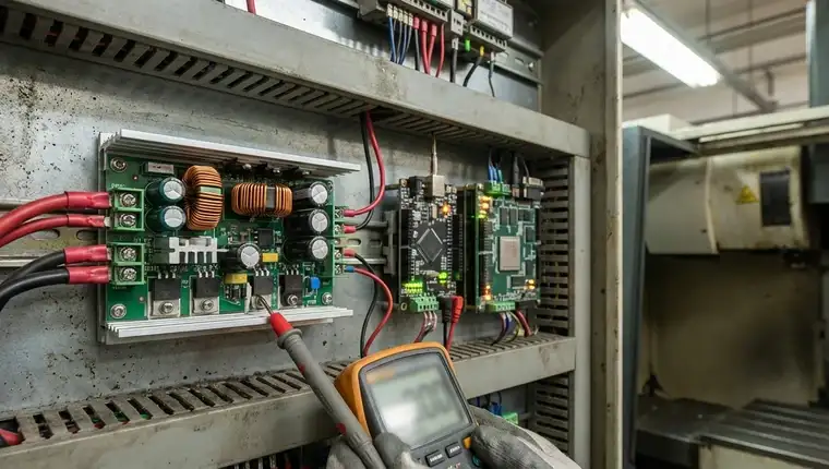
A dc voltage buck converter steps down DC input to a lower output voltage while increasing current — the core tradeoff that defines every topology choice in this category. Whether you’re specifying a converter for an SMPS rail, a battery-powered embedded system, or an industrial control circuit, the right type depends on load profile, switching frequency tolerance, efficiency targets, and how tightly output voltage must be regulated.
Not all buck converters are built for the same job. Synchronous designs trade component cost for efficiency at high loads; asynchronous topologies stay simpler but lose ground under heavy current. Beyond topology, specs like input voltage range, output ripple, and thermal envelope determine fit — and for AC-side voltage regulation challenges, a different class of solution may be more appropriate entirely. This guide walks through the decision criteria so you can shortlist with confidence.
What a DC Voltage Buck Converter Actually Does
A dc voltage buck converter is a switching DC-to-DC converter that steps down input voltage to a lower output voltage while proportionally increasing current — power in equals power out, minus switching losses. This is the fundamental tradeoff that separates it from every other regulation topology.
The Switching Mechanism
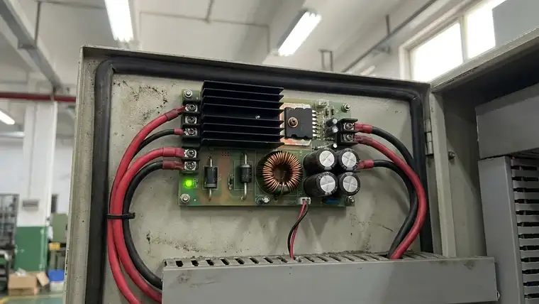
The core circuit is four components: a MOSFET switch, an inductor, a freewheeling diode, and an output capacitor. The MOSFET switches on and off at high frequency (typically 100 kHz–2 MHz). When on, current builds through the inductor toward the load. When off, the inductor’s stored energy continues driving current through the diode to the output. The capacitor smooths the resulting ripple. Output voltage is set by duty cycle — the ratio of on-time to total switching period: V_out = D × V_in.
How It Differs from Linear Regulators and Boost Converters
A linear regulator (LDO) dissipates excess voltage as heat — simple, but inefficient under large voltage differentials. A buck converter recycles energy through the inductor, achieving 85–95% efficiency in well-designed implementations. A boost converter does the inverse: it steps voltage up while reducing current. The buck is strictly step-down only; if your output must exceed input at any point, you need a buck-boost topology instead.
IEC 60038 and Input Tolerance
IEC 60038 defines standard DC voltages and specifies that equipment must tolerate ±10% input variation from the rated value. This is the practical design floor for any dc voltage buck converter in industrial or grid-connected applications — the converter must regulate cleanly across that full input swing without output deviation. A converter rated for 24 V DC input must handle 21.6 V to 26.4 V without losing regulation.
Where Buck Converters Appear
- SMPS circuits: Point-of-load regulation from an intermediate bus (48 V → 12 V → 3.3 V)
- Embedded systems: MCU and FPGA core voltage rails from a higher system supply
- Battery-powered devices: Extending runtime by efficiently stepping Li-ion voltage down to logic levels
- Industrial control: 24 V DC bus to 5 V sensor rails in PLCs and field devices
This switching topology is the baseline against which synchronous, asynchronous, and integrated buck regulator variants are compared — which is where the real selection decisions begin.
Who Actually Needs One — and What Decision They’re Facing
Three types of engineers reach for a dc voltage buck converter: SMPS designers building point-of-load rails from an intermediate bus, embedded system engineers stepping down a system supply to MCU or FPGA core voltages, and industrial power system integrators converting a 24 V DC field bus to 5 V sensor rails in PLCs and control cabinets. The buying job is the same across all three — pick the right topology and implementation form before committing to a layout or BOM.
Synchronous vs. Asynchronous: The First Fork
The topology decision comes first. An asynchronous buck uses a passive freewheeling diode — simpler, cheaper, and adequate for light-to-medium loads where diode conduction losses are acceptable. A synchronous buck replaces that diode with a second MOSFET, cutting conduction losses and pushing efficiency above 90% at high load currents. If your output current exceeds roughly 3–5 A continuously, synchronous is almost always the right call. Below that threshold, asynchronous keeps the design simpler without meaningful efficiency penalty.
Integrated IC Regulator vs. Discrete Module
The second decision is implementation form. A buck regulator IC (from TI, Analog Devices, Monolithic Power) integrates the controller and often the MOSFETs into a single package — compact, well-characterized, but requires external inductor and capacitor selection. A buck converter module (pre-built PCB assembly) ships with all passives included, trading design flexibility for faster time-to-board. Modules suit prototyping or low-volume industrial builds; ICs suit production SMPS designs where BOM cost and footprint matter.
Buck Regulator vs. Buck Converter: Terminology Matters
These terms are often used interchangeably, but the distinction is real. A buck regulator typically refers to the control IC alone — it needs external passives to function. A buck converter refers to the complete switching circuit, whether discrete or modular. When sourcing, the label on a datasheet tells you what you’re actually buying.
When AC Voltage Stabilizers Are the Right Answer Instead
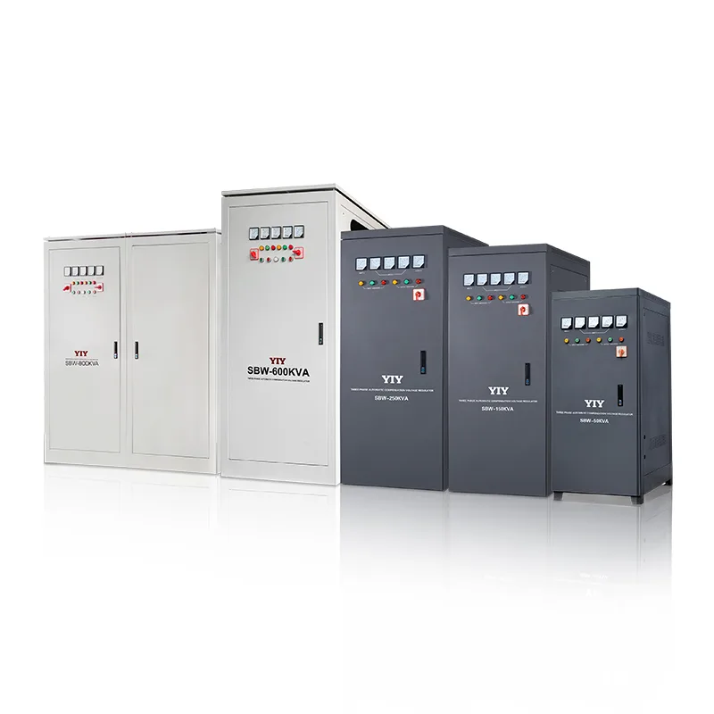
If your problem is AC mains fluctuation — grid voltage swinging ±15% and damaging sensitive equipment — a dc voltage buck converter is the wrong tool entirely. That’s the domain of AC voltage stabilizers: Servo types for industrial loads needing continuous regulation, Relay types where fast step response matters, and IGBT-based units for mission-critical precision. Buck converters operate strictly on the DC side; they cannot regulate AC input or replace a stabilizer upstream of a rectifier stage.
Synchronous vs. Asynchronous: The Topology Tradeoff
The first real design decision in any dc voltage buck converter project is topology: synchronous or asynchronous. Both step down voltage using the same inductor-capacitor core, but they handle the freewheeling current path differently — and that difference drives efficiency, cost, and application fit.
The Core Difference
An asynchronous buck uses a Schottky diode as the freewheeling element. Simple, robust, and cheap — but the diode has a fixed forward voltage drop (~0.3–0.5 V), which becomes a meaningful conduction loss at higher currents. An synchronous buck replaces that diode with a second low-RDS(on) MOSFET. The MOSFET’s resistive drop scales with current rather than staying fixed, which cuts conduction losses significantly at medium-to-high loads and pushes efficiency above 90%.
Efficiency Across Load Ranges
This is where the topology choice gets nuanced. Synchronous converters win at medium-to-high loads — typically above 30–40% of rated current — where MOSFET conduction losses stay low and the efficiency advantage is real. But at light loads, the picture flips: the synchronous MOSFET’s gate drive overhead and body diode reverse recovery losses can actually make it less efficient than a simple Schottky diode. Asynchronous designs handle light-load and low-output-voltage applications better, and they’re the default choice for outputs below ~1 V where diode drop is proportionally smaller.
Comparison Table
| Topology | Efficiency | Cost | Best For |
|---|---|---|---|
| Synchronous | >90% at medium-to-high load | Higher (2 MOSFETs + driver) | High-current rails, battery-powered systems, SMPS point-of-load |
| Asynchronous | 80–88% typical | Lower (1 MOSFET + diode) | Light loads, low-voltage outputs, cost-sensitive designs |
Drawbacks of Buck Converters (Both Topologies)
Do buck converters waste electricity? Less than linear regulators — but not zero. Switching losses, gate drive power, and inductor core losses all contribute. At 85–92% efficiency, 8–15% of input power becomes heat. Beyond efficiency, both topologies share structural drawbacks:
- Switching noise and EMI: The fast MOSFET transitions generate high-frequency noise that requires careful PCB layout and filtering.
- Minimum load requirement: Many buck converters need a minimum load current to maintain regulation — drop below it and output voltage can rise uncontrolled (especially in discontinuous conduction mode).
- Component count: Even a basic asynchronous design requires inductor selection, output capacitor sizing, and compensation network tuning. Synchronous designs add gate driver complexity.
The practical rule: if your continuous load current exceeds ~3 A, synchronous wins on efficiency. Below that, asynchronous keeps the design simpler without meaningful penalty.
Key Specs to Evaluate Before You Specify
Before committing to a part number or module, five parameters determine whether a dc voltage buck converter will actually work in your application — or fail under real operating conditions.
Input Voltage Range and Dropout Headroom
The converter’s input range must cover your source voltage across its full tolerance band. IEC 60038 sets the baseline: equipment must tolerate ±10% of rated input. A 24 V DC bus therefore swings from 21.6 V to 26.4 V — your converter must regulate cleanly across that entire range. The minimum input voltage also sets your dropout constraint: the converter needs enough headroom above the output to maintain regulation. For a 5 V output, you need V_in(min) comfortably above 5 V plus the converter’s minimum dropout voltage (typically 0.5–2 V depending on topology).
Output Current Rating and Thermal Derating
Rated output current is a 25°C number. At elevated ambient temperatures — common in industrial enclosures — you must derate. A converter rated at 5 A may only deliver 3.5 A reliably at 70°C ambient. Check the derating curve in the datasheet, not just the headline spec. For IEC-compliant industrial designs, size for the derated current at your worst-case thermal condition, not the peak rating.
Switching Frequency Tradeoffs
Higher switching frequency (500 kHz–2 MHz) allows smaller inductors and output capacitors, reducing board footprint. The cost is higher switching losses and increased EMI — both matter in noise-sensitive industrial environments. Lower frequency (100–300 kHz) reduces switching losses and simplifies EMI filtering but requires larger passives. The practical rule: go higher frequency when board space is constrained; go lower when thermal budget or EMI compliance is the binding constraint.
Duty Cycle Calculation: 12V to 5V Example
Duty cycle is the first calculation in any buck converter design. The formula is straightforward:
D = V_out / V_in = 5 V / 12 V = 0.417
This means the switch is on 41.7% of each cycle. For a 24 V to 3.3 V rail: D = 3.3 / 24 = 0.138 — a low duty cycle that stresses the converter’s minimum on-time spec and can push it into discontinuous conduction mode at light loads. Always verify the converter supports your required duty cycle range, especially at the extremes of your input voltage window.
Buck Regulator vs. Buck Converter: Read the Datasheet Label
These terms are not interchangeable on spec sheets. A buck regulator IC is the controller only — it requires external inductor, capacitors, and sometimes MOSFETs. A buck converter module is a complete circuit: controller, MOSFETs, inductor, and capacitors integrated into one package. When sourcing, the label tells you what you’re actually buying. Regulator ICs offer more design flexibility and lower BOM cost at volume; converter modules reduce design time and are the faster path to a working prototype.
Where Voltage Stabilizers Fit When Buck Converters Don’t
A dc voltage buck converter solves one specific problem: stepping down DC input to a lower DC output. It operates entirely on the DC side of the power chain. When the problem shifts upstream — to AC grid instability, mains voltage swinging ±15–20% due to weak infrastructure or heavy industrial loads — a buck converter is the wrong tool entirely. That’s a different failure mode requiring a different class of solution.
The AC vs. DC Boundary
Buck converters regulate DC rails. AC voltage stabilizers regulate AC input. These are not interchangeable. If your equipment is failing because the mains supply fluctuates between 180 V and 250 V on a nominal 220 V grid, no DC converter upstream of your rectifier will fix that — you need an AC stabilizer before the power enters your system. The problem is on the grid side, not the DC rail side.
Three Technologies for AC Regulation
Once you’ve confirmed the problem is AC input instability, the technology choice mirrors the same tradeoff logic you’d apply to DC converters:
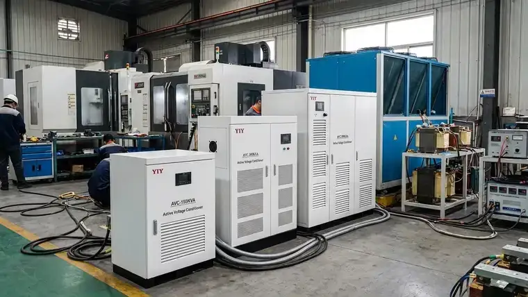
Servo stabilizers use a motorized variac to continuously adjust output voltage. They offer the best balance of regulation accuracy, load range, and cost for general industrial use — CNC machines, HVAC systems, production lines. Most industrial deployments default here.
Relay stabilizers switch between transformer taps in discrete steps. Response is fast — typically under one cycle — making them the right choice for dynamic loads where voltage spikes and sags happen quickly. The tradeoff is stepped (not continuous) regulation.
IGBT stabilizers use solid-state switching for near-instantaneous, continuously variable regulation with output accuracy of ±1% or better. The right answer for mission-critical equipment: medical imaging, semiconductor fabrication, precision metrology. Higher cost, highest precision.
Where YIY Fits Against the Competition
Most AC stabilizer suppliers are single-technology or single-market. Servomax, for example, focuses on servo and transformer-based units with a primarily India-centric distribution footprint. Many regional manufacturers offer relay or servo types only, with no IGBT capability and no OEM/ODM path.
YIY covers the full stack — Servo, Relay, and IGBT technologies — across a range from 0.5 KVA to 3000 KVA, exported to 130+ countries. For procurement teams sourcing across multiple sites or product lines, that matters: one qualified supplier, one audit, one relationship, regardless of whether the application calls for a relay unit in a warehouse or an IGBT stabilizer in a cleanroom. OEM/ODM customization is available for integrators who need branded or application-specific configurations — a capability most competitors in this space don’t offer at scale.
FAQ: Common Questions on Buck Converter Selection
When should you use a buck converter?
Use a buck converter when your load requires a DC voltage lower than your source — stepping 12 V down to 5 V, or 48 V down to 3.3 V. It’s the right choice when efficiency matters and you can tolerate switching noise. If your output must ever exceed your input, you need a buck-boost topology instead.
What are the drawbacks of a buck converter?
Three structural limitations apply to every topology. First, EMI: fast MOSFET switching generates high-frequency noise that requires careful PCB layout and filtering — a real constraint in noise-sensitive industrial environments. Second, minimum load requirement: many designs need a baseline load current to maintain regulation; drop below it and output voltage can rise uncontrolled. Third, complexity vs. linear regulators: a buck converter requires inductor selection, capacitor sizing, and compensation tuning. An LDO is simpler — just not efficient under large voltage differentials.
Do buck converters waste electricity?
Less than linear regulators, but not zero. A well-designed synchronous buck runs at 88–95% efficiency; 5–12% of input power becomes heat through switching losses, gate drive overhead, and inductor core losses. At equivalent load, a linear regulator dissipating a 7 V drop at 2 A wastes 14 W as heat. The same conversion in a buck converter wastes under 2 W. Efficiency is real — but it’s not 100%.
Can you build a simple buck converter yourself?
The basic circuit — MOSFET, inductor, diode, capacitor — is straightforward on paper. In practice, inductor selection, compensation network tuning, and EMI layout make discrete designs time-consuming to get right. For most applications, an integrated buck regulator IC (TI, Analog Devices, Monolithic Power) is the faster and more reliable path. The IC handles control and protection; you select the external passives from the datasheet’s application circuit.
What about AC-side voltage problems?
If your equipment is failing because mains voltage fluctuates — not because a DC rail is out of spec — a buck converter won’t help. That’s an AC regulation problem requiring a voltage stabilizer upstream of your rectifier. The right technology depends on load profile and precision requirements: Servo for general industrial use, Relay for fast-response dynamic loads, IGBT for mission-critical precision.
What are the drawbacks of a buck converter?
Buck converters introduce switching noise (EMI), require careful PCB layout, and have efficiency losses at light loads. They also need an inductor and capacitors, adding BOM complexity. For noise-sensitive analog circuits, an LDO may be preferable despite lower efficiency.
When to use a buck converter?
Use a buck converter when input voltage is higher than output voltage, load current exceeds ~100mA, and efficiency matters. Common applications: 12V to 5V, 24V to 3.3V, battery-powered systems, and industrial DC rails.
If you’re evaluating AC voltage stabilization options and want a comparison grounded in tradeoffs rather than a product pitch, YIY’s engineering team offers consultation across Servo, Relay, and IGBT technologies — covering proof points, application fit, and shortlist criteria for your specific load and site conditions.
Frequently Asked Questions
When should I use a buck converter instead of a linear regulator?
Use a buck converter when efficiency matters and your input-to-output voltage differential is large. A linear regulator dissipates the excess voltage as heat — at 2 A with a 7 V drop, that’s 14 W wasted. A buck converter handling the same conversion loses under 2 W. The tradeoff: buck converters require inductor and capacitor selection, and they generate switching noise. If your voltage differential is small (under 1–2 V) and load current is low, an LDO is simpler and the efficiency gap closes. Once you’re stepping down more than a few volts at meaningful current, the buck converter wins on thermal budget alone.
What are the main drawbacks of a DC voltage buck converter?
Three structural limitations apply regardless of topology. First, EMI: fast MOSFET switching generates high-frequency noise that requires careful PCB layout and output filtering — a real constraint in noise-sensitive industrial environments. Second, minimum load requirement: many designs need a baseline load current to maintain regulation; drop below it and output voltage can rise uncontrolled, especially in discontinuous conduction mode. Third, design complexity: even a basic implementation requires inductor sizing, output capacitor selection, and compensation network tuning. An integrated buck regulator IC reduces this burden significantly, but it doesn’t eliminate it.
How do I size a buck converter for my application?
Start with duty cycle: D = V_out / V_in. For a 12 V to 5 V conversion, D = 0.417 — the switch is on 41.7% of each cycle. Then size for derated output current at your worst-case ambient temperature, not the headline spec at 25°C. In industrial enclosures, a converter rated at 5 A may only deliver 3.5 A reliably at 70°C. Finally, confirm the converter’s input range covers your full source tolerance — IEC 60038 requires ±10% input variation handling, so a 24 V nominal bus must be sized for 21.6 V to 26.4 V.

What is the difference between a buck regulator and a buck converter?
A buck regulator is the control IC — it needs external passives (inductor, capacitors, sometimes MOSFETs) to function. A buck converter is the complete switching circuit, whether discrete or packaged as a module. When sourcing, the datasheet label tells you what you’re actually buying. Regulator ICs offer more design flexibility and lower BOM cost at volume; converter modules reduce design time and are the faster path to a working prototype.
Final Thoughts
Topology choice comes down to load profile and efficiency target: synchronous wins above ~3 A continuous, asynchronous keeps things simpler below that threshold. Spec selection depends on your input voltage range, IEC 60038 compliance requirements, and thermal derating at real operating temperatures — not the headline numbers. If your problem is AC grid instability rather than a DC rail out of spec, a buck converter won’t solve it; that’s a voltage stabilizer problem upstream of your rectifier.
If you’re working through these tradeoffs and want a second opinion on shortlist criteria — whether that’s DC-side spec validation or AC stabilizer technology selection — YIY’s engineering team offers comparison-based consultation across Servo, Relay, and IGBT technologies, grounded in proof points rather than a product pitch.
About YIY
Zhejiang Yiyen Holding Group Co., Ltd. (YIY) is a professional voltage stabilizer manufacturer with 16+ years of experience. With a 30,000sqm modern facility and an annual production capacity of 1,000,000+ units, our products are exported to 130+ countries. We provide OEM/ODM customization services and are ISO 9001:2015 certified, committed to delivering stable and reliable voltage protection solutions to global customers.
Contact Us
Email: yiyen@yiyen.com
Phone/WhatsApp: +86 13587452904
Website: https://www.yiyavr.com/
If you found this article helpful, contact us for a sizing review or customized solution.
Related reading: How Voltage Stabilizer Works: Relay, Servo & IGBT Guide.