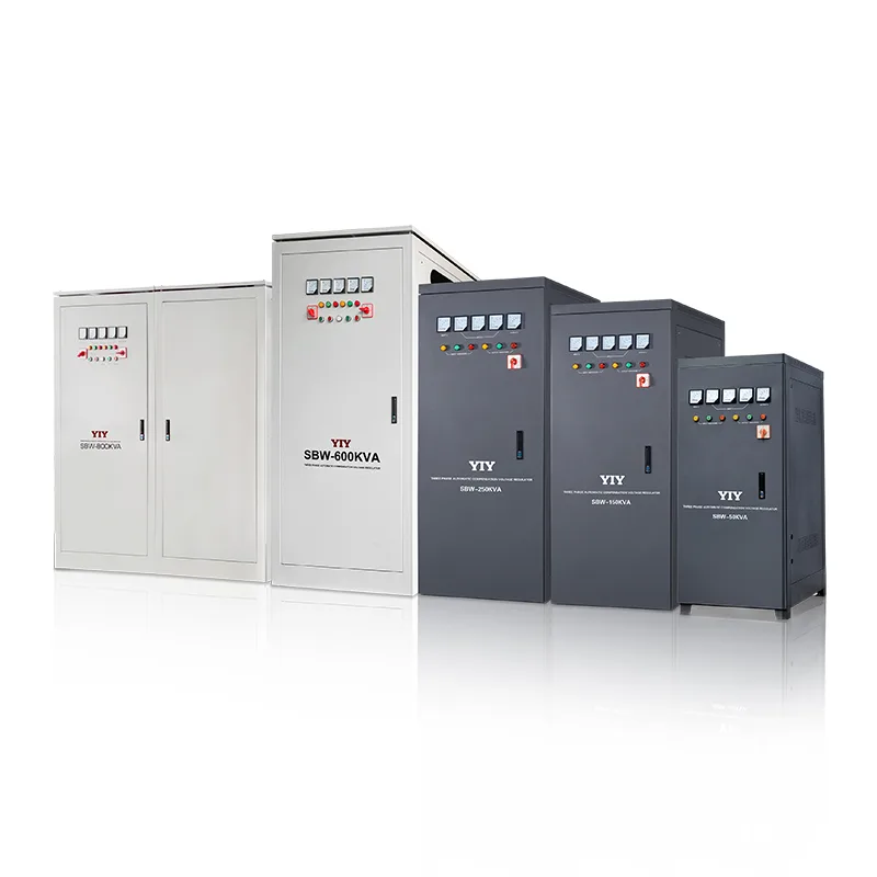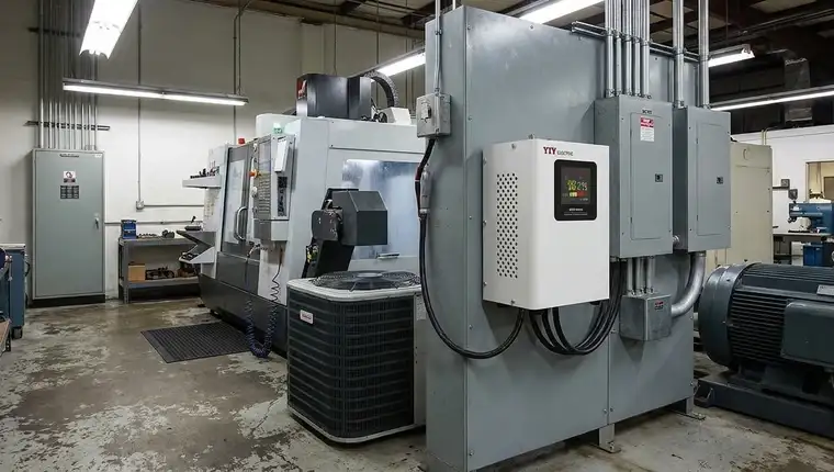
If you are buying a servo stabilizer 10kva 3 phase, you must compare real inrush behavior, measured grid variance, and output precision rather than relying solely on nominal kVA ratings. Engineering audits indicate that undersizing due to unverified phase imbalance drives nearly 30% of premature equipment failures across mid-range installations.
When you evaluate a unit for your facility, prioritize these engineering metrics over marketing claims. Throughout this guide, I will walk you through capacity planning, topology selection, phase balance trade-offs, and the exact verification steps you should take before issuing an RFQ.
When Should You Decide to Procure a Servo Stabilizer 10Kva 3 Phase?
You should only initiate procurement when your facility’s mains voltage consistently drifts outside standard tolerance bands or phase imbalance threatens your sensitive control networks. A servo stabilizer 10kva 3 phase fits your application when your continuous operating load peaks near 8 kVA while facing input fluctuations of ±15% or more. Real site conditions dictate whether this configuration is the correct engineering intervention, rather than relying on generic catalog labels or historical purchasing habits.
Nominal kVA ratings frequently mislead selection teams because they ignore the actual electrical footprint and power factor of your connected equipment.
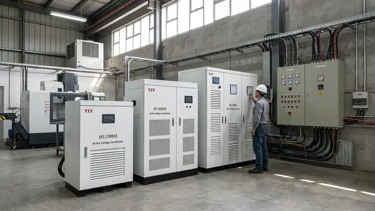
If your load profile includes frequent inductive startups, the continuous nameplate power reveals little about your instantaneous surge capacity. When you apply a 20–25% safety margin to your baseline draw, your machinery stabilizes safely without triggering nuisance trips. This capacity math means your unit must handle brief apparent power surges approaching 12.5 kVA while your downstream control loops reset. Tracking your actual peak usage over a standard operating cycle establishes the true baseline before you finalize vendor specifications.
Aligning these hardware checks with verified Three-Phase Voltage Stabilizers documentation ensures your team receives equipment engineered for predictable service intervals and stable phase symmetry.
Grid instability amplifies these risks when local distribution networks experience phase imbalances exceeding 5% or frequent momentary interruptions. According to the IEC 60038 standard voltage framework, maintaining strict voltage windows remains essential for equipment longevity and regulatory compliance. When you ignore variance patterns during specification, undervoltage events silently degrade motor windings or corrupt sensitive logic controllers. You must audit your incoming lines for these specific variance patterns before issuing purchase orders to guarantee safe, uninterrupted operations.
| Load Type | Sensitivity Profile | Recommended Safety Margin |
|---|---|---|
| CNC Machines | Tolerant to minor ripple; requires rapid brush adjustment | 25% above peak current |
| HVAC Compressors | Heavy inductive startup; vulnerable to prolonged undervoltage | 15–20% above continuous draw |
| IT Servers / PLCs | Demands ultra-tight regulation and fast response times | 10% with priority on settling precision |
Modern deployments also require you to factor environmental stress and operational visibility into the evaluation. If your installation faces high dust or elevated heat, specifying IP40+ enclosures and optimized airflow prevents thermal derating. You should also verify that your chosen model supports remote monitoring and event logging, allowing your maintenance staff to catch grid fluctuations before they disrupt production yields.
How Does Servo Control Logic Solve Industrial Voltage Swings?
To protect your equipment effectively, you rely on servo control logic that continuously monitors input variance and dynamically adjusts an autotransformer’s turns ratio via a motor-driven variac. When you size a 10 kVA three-phase unit, understanding this closed-loop sequence proves essential for matching hardware to your actual load sensitivity. The process starts with a high-speed microcontroller sampling your incoming line voltage, capturing microsecond-scale sags before they reach your downstream panels.
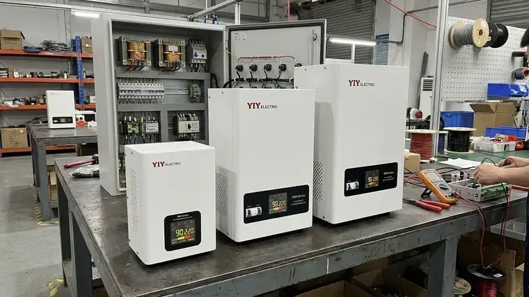
The motor-driven variac then glides a carbon brush along the winding to seamlessly adjust the turns ratio. In practice, this means your control networks receive smooth stepless regulation instead of the abrupt switching that triggers nuisance trips.
You can track the operational flow through four integrated phases:
• Real-Time Sampling: The MCU reads phase data at intervals below 10 milliseconds.
• Deviation Calculation: Embedded algorithms compare live metrics against your set target thresholds.
• Motor Actuation: Pulse-width signals drive the variac brush to physically shift the winding ratio.
• Closed-Loop Verification: Output sensors confirm stability before the controller locks the brush position.
According to the IEC 60000-4-11 voltage dip testing framework, optimized servo configurations typically deliver correction speeds between 1.0 and 1.5 seconds for input variations while maintaining tight regulation. This rapid settling guarantees that mixed inductive loads stabilize within acceptable bands before protective relays trip. When you calculate unplanned downtime costs, shaving fractions of a second off response periods directly prevents costly machine lockouts.
For dusty or high-heat shop floors, you must pair this control architecture with proper environmental shielding. Specifying IP54-rated enclosures with isolated ventilation channels prevents conductive particulate buildup on the brush assembly. Modern systems route alarms to your central control room, ensuring your maintenance staff catch grid excursions before they disrupt production cycles.
Why Does the Three-Phase Topology Outperform Single-Phase at This Power Class?
When you deploy a 10 kVA unit for mixed industrial loads, the three-phase topology matters because it balances current distribution across all lines, reduces per-phase thermal stress, and delivers higher conversion efficiency than single-phase alternatives. You distribute apparent power evenly across three conductors using 120-degree electrical intervals, which prevents isolated components from overheating during continuous operational cycles.
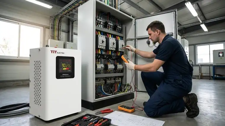
This capacity tier aligns directly with standard nominal ratings like 208 V, 400 V, and 480 V. In practice, this international alignment means your stabilizer operates within recognized tolerance windows, simplifying compliance reviews and matching your existing switchgear specifications without requiring custom adapters. If your facility runs a single-phase equivalent at this power class, your distribution panels handle higher per-leg currents, which increases cable heating and compounds your baseline energy consumption.
Understanding how phase balance protects your downstream equipment reveals why a shared topology is superior:
– Per-Phase Current Sharing: Inductive loads draw power in staggered intervals, preventing sudden voltage sags that would otherwise trip your sensitive PLC networks.
– Neutral Conductor Management: A properly balanced configuration keeps neutral current near zero, minimizing harmonic distortion that typically overheats legacy control wiring.
– Thermal Efficiency: Distributing the total footprint across three independent windings lowers aggregate copper losses, allowing your unit to maintain safe internal temperatures without oversized auxiliary fans.
If your installation faces persistent grid swings or elevated ambient heat, you must prioritize sealed enclosures paired with humidity-resistant conformal coatings. Verifying actual current mapping safeguards your production throughput and delivers a measurable return on your capital protection investments.
What Specification and Maintenance Checkpoints Must You Verify Before Purchase?
You must confirm input tolerance, thermal protection thresholds, brush service intervals, and certified manufacturing compliance before issuing any purchase order. Direct engineering validation at this stage prevents misaligned hardware that typically drives premature servo failures in mixed-load environments.
When evaluating the vendor shortlist, you need a structured procurement screen to weigh these specifications against your site conditions:
| Check | Why it matters | If you skip it |
|---|---|---|
| Input voltage window & boost-buck range | Matches the unit’s mechanical limits to your actual grid variance | Core saturation or failure to correct severe sags during peak shifts |
| Overload & short-circuit protection | Guarantees surge tolerance and millisecond trip curves for motor startups | Winding insulation breakdown and extended line lockouts |
| Carbon brush inspection intervals | Maintains long-term regulation accuracy and prevents track scoring | Precision drift and costly downtime due to sudden electrical arcing |
| Quality & environmental compliance | Verifies adherence to established manufacturing and safety protocols like ISO 9001:2015 | Unverified tolerances that fail regulatory audits or void warranties |
Carbon brush wear dictates your long-term regulation accuracy, so you should select suppliers who publish transparent replacement schedules instead of vague maintenance advisories. If your load profile requires scaling beyond baseline 10kVA thresholds, evaluating adjacent capacity bands using a 20kva voltage stabilizer ensures your infrastructure supports seamless future expansions without compromising phase balance. Tracking your actual peak usage over a standard operating cycle establishes the true baseline before you finalize vendor specifications.
You can follow our detailed 3 phase main line stabilizer sizing framework to map your exact load requirements to the correct hardware footprint.
Frequently Asked Questions
How Does a 10 kVA Three-Phase Servo Stabilizer Handle Sudden Load Changes?
A motor-driven autotransformer with an integrated MCU continuously adjusts the carbon brush position to maintain output stability during inductive surges. When your compressor starts, the closed-loop logic redistributes current across all three phases to prevent downstream voltage sags. You must confirm the vendor guarantees a minimum overload capacity of 130% for at least 60 seconds, allowing your heavy machinery to stabilize safely before the system locks out.
What Is the Expected Response Time for Servo Stabilizers in This Capacity Tier?
A servo unit settles in a second or so rather than milliseconds, because the brush has to travel physically along the winding. Speed depends on the motor, the control loop and how far the input has moved. Ask the vendor for a test report showing correction time for a stated input step, not a brochure figure.
What Is the Difference Between Single-Phase Stabilizer and 3 Phase Stabilizer?
A single-phase unit corrects one live line and suits light commercial loads. A three-phase unit corrects all three lines, so it serves three-phase motors and spreads the load over three windings, which keeps per-phase heating and neutral current lower. Check that the panel actually carries a reasonably balanced three-phase load before you choose it.
How Should You Compare Pricing for Servo Stabilizer Three Phase Stabilizer?
Procurement decisions must weigh total lifecycle costs against baseline quotes, factoring in copper winding quality, solid-state control boards, and enclosure IP ratings. Cheaper models often omit critical thermal protections, leading to higher long-term energy consumption and frequent component swaps. You should request a detailed bill of materials and cross-reference the manufacturer’s ISO certificates with their warranty terms to validate true manufacturing quality before signing a purchase order.
Final Thoughts
Selecting the correct configuration requires matching your verified inrush peaks and local grid variance bands instead of relying on nameplate ratings alone. When you align this capacity tier with your actual operating footprint, you prevent silent phase imbalance and protect downstream logic controllers from costly production lockouts. Start with a low-friction first-pass review by cross-referencing your panel’s continuous draw against the unit’s surge tolerance window.
If your project demands broader engineering validation or you want to evaluate larger alternatives before committing, review our guide on how to compare before buying a voltage stabilizer to solidify your decision matrix. Once the baseline matches your needs, submit your detailed load schedules and ambient site conditions to our engineering team for a formal technical sizing assessment.
About YIY
Zhejiang Yiyen Holding Group Co., Ltd. (YIY) is a professional voltage stabilizer manufacturer with 16+ years of experience. With a 30,000sqm modern facility and an annual production capacity of 1,000,000+ units, our products are exported to 130+ countries. We provide OEM/ODM customization services and are ISO 9001:2015 certified, committed to delivering stable and reliable voltage protection solutions to global customers.
Contact Us
Email: yiyen@yiyen.com
Phone/WhatsApp: +86 13587452904
Website: https://www.yiyavr.com/