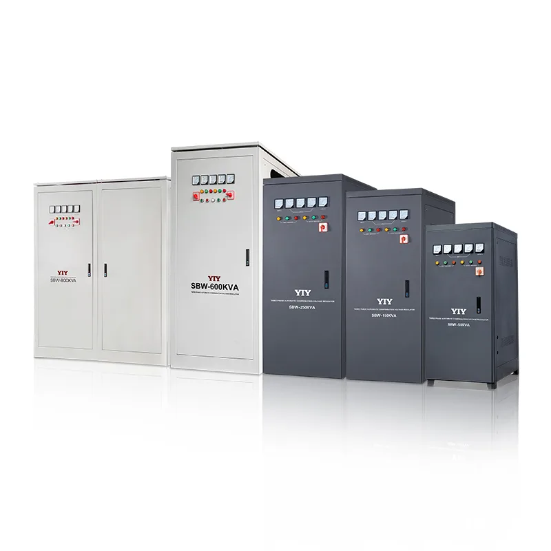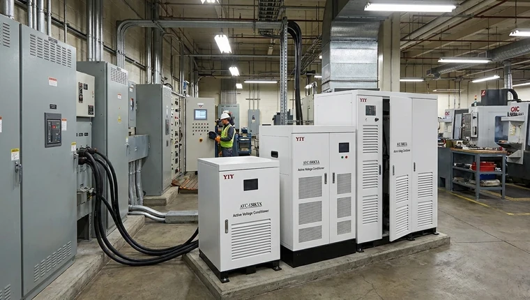
A servo stabilizer three phase fits industrial loads that need continuous voltage correction, balanced output, and practical cost control. Start with real load kVA, starting current, input-voltage range, phase imbalance, cooling conditions, and bypass needs—not catalog capacity alone.
Once the load profile and correction method are clear, compare the complete servo voltage stabilizer range by phase, capacity, input window, output accuracy, cooling, and bypass requirements.
What Does A Servo Stabilizer Three Phase Do For Your Load?
You use this type of stabilizer when your three-phase supply fluctuates enough to affect motors, drives, PLCs, compressors, or process equipment. A three-phase servo voltage stabilizer monitors incoming voltage, compares it with your target output, and drives a servo motor to adjust an autotransformer ratio so your downstream equipment receives a more stable supply.
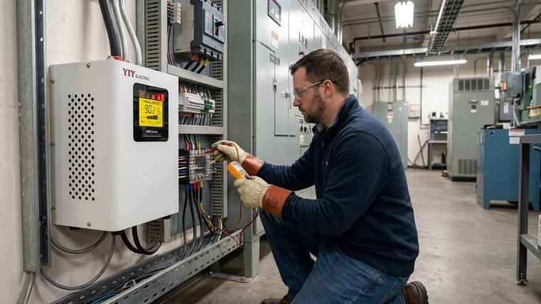
For industrial loads, this matters because voltage problems are rarely limited to one clean number. Your site may have undervoltage during peak shifts, overvoltage during light-load periods, unequal line-to-line voltage, or short dips when large motors start. A properly selected stabilizer helps reduce nuisance trips and protects equipment from operating outside its preferred voltage window.
Why do three-phase loads trip when the grid is unstable? Deep sags and phase unbalance are the usual causes. A dip lasting a few cycles can reset PLCs and drop contactors, and the line stops until someone clears the fault. Unbalanced supply makes induction motors draw uneven winding current, so they run hotter than their nameplate assumes and wear bearings and insulation faster.
Surge suppressors don’t help here: they clip spikes but leave sustained RMS drops untouched. Formal dip immunity is tested under IEC 61000-4-11:2020, and a stabilizer with event logging shows you which of those events actually reach your line.
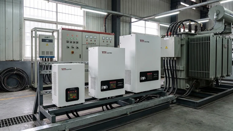
How Does A Three-Phase Servo-Controlled Stabilizer Work?
You get continuous correction because the servo motor moves a carbon brush across an autotransformer instead of jumping between fixed relay taps. The controller samples voltage, calculates the error from your setpoint, and commands the motor to adjust the transformer turns ratio until output returns to the target range.
A simplified correction sequence looks like this:
- MCU sampling: Your stabilizer control board reads incoming voltage repeatedly.
- Error calculation: The controller compares measured voltage with the required output voltage.
- Servo actuation: The servo motor moves the carbon brush along the autotransformer winding.
- Ratio adjustment: The transformer bucks or boosts voltage until the output stabilizes.
For you, the important point is that correction is smooth rather than stepped. Relay stabilizers switch between taps, which may be acceptable for simple loads, but industrial control systems often prefer gradual correction because abrupt steps can disturb sensitive electronics.
Servo correction is mechanical, so it is slower than static electronic designs. For many industrial loads it still gives a practical balance of precision, capacity range, serviceability, and cost. Keep normal fluctuation correction separate from short-duration immunity: the stabilizer corrects the supply, but connected equipment immunity still depends on its own design.
The brush and its track are the main wear items. Inspection intervals, wear limits, and spare stocking are covered in the servo stabilizer carbon brush guide.
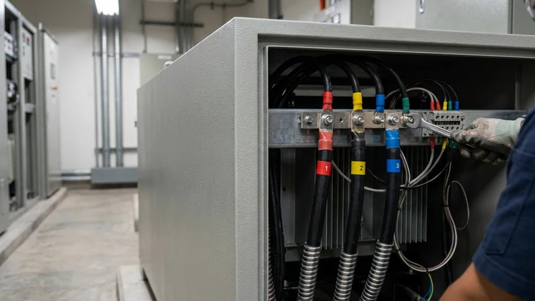
When Should You Choose Servo Instead Of Relay Or Static Technology?
You should choose servo when your industrial load needs tighter correction than relay designs usually provide, but you do not require the fastest electronic response of a static stabilizer. Servo designs are commonly selected for production machinery, workshops, CNC equipment, compressors, pumps, packaging lines, and mixed industrial loads where stable output and practical maintenance both matter.
The table below compares the selection logic at a buyer level:
| Technology | How it corrects voltage | Strength for your load | Limitation to check | Typical fit |
|---|---|---|---|---|
| Relay stabilizer | Switches fixed taps | Lower cost and simple structure | Stepped output and contact wear under frequent switching | Light commercial loads, basic equipment |
| Servo stabilizer | Motor-driven brush adjusts autotransformer ratio | Smooth correction, good precision, scalable capacity | Brush and motor require periodic inspection | Industrial machinery, motors, CNC, plant distribution |
| Static stabilizer | Electronic switching and control | Very fast response and high precision | Higher cost, heat management, filtering needs | Highly sensitive electronics, selected precision environments |
For you, the decision depends on load behavior. If your machines tolerate stepped correction and your budget is tight, relay may be enough. If your process cannot tolerate voltage dips or very fast disturbances, static regulation may be worth evaluating. If your load is a general industrial mix with motors and control electronics, a three phase servo controlled voltage stabilizer often gives the most practical middle ground.
Which Sizing Checks Matter Before You Specify A 3 Phase Servo Stabilizer?
You should size the stabilizer from measured load and site conditions, then add margin for starting current and future load changes. A catalog rating only tells you what the unit can carry under defined conditions; your actual plant may impose higher stress through motor starts, heat, dust, voltage sag, or phase imbalance.
1. Running KVA
Start with your real connected load, then identify which equipment operates at the same time. If you only add every nameplate together, you may oversize. If you only consider average running current, you may undersize. Your best estimate is the maximum realistic simultaneous load.
For three-phase apparent power, use:
kVA = √3 × line voltage × line current ÷ 1000
For you, this formula converts measured voltage and current into the stabilizer capacity language suppliers use. For example, if your measured three-phase current is high during peak operation, that peak—not the quiet-shift average—should guide sizing.
If your load list is in kW, convert first: kVA = kW ÷ power factor. A 15 kW running load at 0.8 power factor is 18.75 kVA, so a 20 kVA unit is already tight before starting current, sag, ambient heat, and expansion are counted.
In the 10–30 kVA class, a 10 kVA unit usually suits a small machine group or light panel, 20 kVA a moderate mixed load when starting margin is acceptable, and 30 kVA a heavier feeder or one with planned expansion.
2. Starting Current And Inductive Load Margin
Motors, compressors, pumps, and some machine tools draw much higher current at startup than in steady operation. Add a starting-current margin above running kVA, and base it on your measured start data or the motor maker’s starting current rather than a fixed rule of thumb.
The starting method matters as much as the motor size: DOL starts stress the stabilizer far more than soft-starter or VFD starts. A unit that looks correct in steady operation can overheat during repeated starts if this margin is skipped.
For feeder-level projects, use the 3 phase main line stabilizer guide after you estimate running kVA and startup margin.
3. Input-Voltage Window
Your stabilizer must cover the low and high voltage actually seen at site. Do not assume nominal voltage is enough. Ask for power quality logs, meter readings, or at least repeated measurements during peak and off-peak periods.
Industrial voltage compatibility context is covered by IEC 61000-2-4 supply voltage compatibility standards. For your practical selection, this means you should compare the stabilizer input range against the real voltage boundary at your facility. If your grid drops below the unit’s correction window, the stabilizer cannot maintain rated output.
Example: if your nominal system is 400 V or 415 V three phase, but your measured input sometimes falls far below that range, you need a wider input design. The exact acceptable range depends on your equipment, local supply, and stabilizer model.
4. Phase Imbalance
A three-phase stabilizer should not be selected only on total kVA. Your phase loading matters. If one phase carries much more load than the others, you may see line-to-line imbalance, neutral stress, and uneven heating.
For you, the practical step is simple: record current on each phase during normal production and during major machine starts. If imbalance is significant, share the readings during technical review so the stabilizer configuration can be matched to real line behavior.
5. Installation Environment
A stabilizer that runs fine in a clean electrical room can struggle in a hot, dusty workshop.
Check the wiring system first. A 3-wire supply is L1-L2-L3 without neutral; a 4-wire supply adds N. Many plants run auxiliary controls, contactors, and lighting phase-to-neutral, so a unit specified for the wrong wiring can leave those circuits unstable even when line-to-line output looks right. A single-phase stabilizer can’t correct a three-phase panel.
| Site condition | What you should check | Why it matters for you |
|---|---|---|
| High ambient temperature | Cooling method and derating | Heat reduces component life and may lower usable capacity |
| Dust or conductive particles | Enclosure protection and maintenance access | Dust can affect brush track, fans, terminals, and insulation surfaces |
| Humidity | Cabinet sealing and anti-condensation measures | Moisture increases tracking, corrosion, and insulation risk |
| Limited maintenance access | Bypass and front-access service layout | Your maintenance team needs safe inspection without disrupting production longer than necessary |
| Main-line installation | Cable size, breaker coordination, ventilation clearance | Incorrect installation can create voltage drop, overheating, or unsafe isolation |
| 3-wire vs 4-wire supply | Neutral need of controls and auxiliary loads | Phase-to-neutral circuits may stay unstable |
| Earthing continuity | Fault clearing and personnel safety | Shock, surge, and fault risk rises |
| Alarm contacts or event logs | Makes voltage events visible to PLC, BMS, or SCADA | Maintenance can’t prove the root cause of trips |
For hot, dusty, or humid sites, specify filters, anti-condensation heaters, corrosion protection, or an IP-rated cabinet where needed. The industrial voltage stabilizer selection guide covers grid logs, cooling, and bypass planning in more depth.
Should You Choose Air-Cooled, Forced-Air, Or Oil-Cooled Construction?
You should choose cooling based on load size, ambient temperature, dust level, and duty cycle rather than assuming one construction is always better. Air-cooled designs are simpler and common for many installations, while oil-cooled construction can be useful when your operating environment or capacity level demands stronger thermal buffering.
| Cooling type | Best fit for your site | What it means in practice | What to verify |
|---|---|---|---|
| Natural or standard air-cooled | Cleaner rooms and moderate ambient temperature | Easier inspection and simpler maintenance | Ventilation clearance, dust control, fan condition if fitted |
| Forced-air cooled | Higher duty cycles or warmer indoor areas | Better heat removal than passive cooling | Fan reliability, filter access, alarm options |
| Oil-cooled | Higher capacity, heavy-duty, dusty, or thermally demanding environments | Oil helps transfer heat and protect windings | Oil quality checks, sealing, service procedure, floor loading |
For you, a three phase servo stabilizer oil cooled unit may be appropriate when the load is heavy, continuous, and exposed to harsher conditions. However, oil cooling also changes maintenance needs. You should confirm oil inspection procedures, leakage control, dielectric testing expectations, and installation space before approving the design.
Which YIY Three-Phase Servo Series Fits Your Application?
Shortlist by load sensitivity, capacity, and measured input range. For general machine rooms, SVC-3 is the practical starting point; move to PRO-3 or PWR-3 when the load needs tighter output, and to SBW for large main-line capacity.
| Series | Published spec (product page) | Typical fit | What to confirm |
|---|---|---|---|
| SVC-3 (TNS) | ±3% output; 100% unbalanced load capability; 278–433 V input option | General industrial distribution, unbalanced panels | kVA, voltage window, bypass, service access |
| PRO-3 | MCU control; ≤2% output precision; 1.5–100 kVA | Precision manufacturing, lab-style loads | Accuracy target, load sensitivity, monitoring |
| PWR-3 | ≤2% precision; 45–150 kVA; 285–475 V or 266–494 V input | Heavy industrial loads on weak grids | Thermal design, input range, cable access |
| SBW | ±3% output; 304–456 V input | Large main-line and plant-level capacity | Cooling, floor loading, breaker coordination |
For dusty, humid, or hot sites, any series may need an adapted enclosure and cooling; for export or OEM projects, confirm nominal voltage, documentation, and acceptance tests in writing.
What Should Your Procurement Checklist Include?
You should use a structured checklist so your supplier quotes the stabilizer your load actually needs. A vague inquiry such as “send price for 30 kVA three phase stabilizer” often leads to missing input range, bypass, enclosure, protection, and installation details.
| Check | Why it matters | If you skip it |
|---|---|---|
| Running kVA and peak current | Confirms real capacity demand | You may underbuy and overheat the unit |
| Starting current of motors/compressors | Captures short-term surge behavior | The stabilizer may trip or sag during startup |
| Input-voltage minimum and maximum | Ensures the correction range covers your grid | Output may drop out of regulation during deep sag |
| Required output voltage | Aligns with your machine and regional standard | Equipment may still see unsuitable voltage |
| Phase imbalance data | Identifies unequal line loading | One phase may remain stressed even after installation |
| Cooling and ambient temperature | Prevents thermal overload | Component life may shorten in hot environments |
| Enclosure and IP requirement | Matches dust, humidity, and installation location | Contamination may increase maintenance and fault risk |
| Manual or automatic bypass | Allows safe maintenance or emergency continuity | You may need a shutdown to service the stabilizer |
| Protection functions | Covers over/under-voltage, overload, delay, phase loss, and alarms | Faults may reach downstream equipment unnoticed |
| Service access and spare parts | Keeps maintenance realistic | Repairs may take longer than expected |
| Power factor and simultaneous loads (#22767) | Converts kW to kVA and drops impossible load combinations | You may overload the unit or pay for capacity you never use |
| Nominal voltage, frequency, 3-wire or 4-wire (#23942) | Matches the supply system, e.g. 380/400/415 V at 50 Hz or 480 V at 60 Hz | Controls or auxiliary loads may not match the output |
| Starting method (#23942) | DOL, star-delta, soft starter, or VFD changes the overload margin | The quote may assume a gentler start than your site has |
| Monitoring (#23942) | Meters, alarms, dry contacts, or remote signals | Voltage events stay invisible to maintenance |
For your RFQ, attach a load list, site voltage readings, single-line diagram if available, installation photos, ambient conditions, and any expansion plans. This information lets the supplier validate whether a standard model is enough or whether your site needs a customized input range, enclosure, transformer design, or bypass arrangement.
Make every supplier answer the same table. If one quotes a wide-input, bypass-equipped unit with independent phase control and another quotes a basic model, the prices aren’t comparable, so compare the technical package before the number at the bottom.
How Should You Verify Installation Before Energizing The Stabilizer?
You should verify phase sequence, grounding, cable termination, bypass status, and output voltage before connecting your production load. A correct stabilizer can still create problems if it is wired into the system incorrectly.
Use this acceptance sequence:
- Confirm nameplate and specification. Match kVA, input range, output voltage, phase, frequency, and wiring configuration against your purchase order.
- Inspect mechanical condition. Check enclosure, ventilation, terminals, indicators, shipping damage, and internal debris before power-up.
- Verify phase rotation. Use a phase sequence meter before energizing motors. For you, this prevents reverse rotation and possible mechanical damage.
- Check grounding and bonding. Measure earth continuity against your site standard and confirm the protective earth conductor is securely connected.
- Confirm neutral requirements. If your model or load requires neutral, verify neutral-to-ground voltage and connection integrity.
- Test bypass operation. Confirm whether the bypass is manual or automatic and make sure operators understand its position.
- Energize without load first. Measure input and output line-to-line and line-to-neutral voltages before connecting production equipment.
- Add load gradually. Watch current, voltage correction behavior, abnormal noise, heating, and alarms during staged startup.
- Record baseline data. Save input voltage, output voltage, load current, ambient temperature, and phase balance for future maintenance comparison.
For you, the baseline record is valuable because it turns future troubleshooting into comparison rather than guesswork. If output voltage changes months later, your maintenance team can compare the new readings with commissioning data.
What Final Checks Should You Complete Before Issuing the PO?
Run seven checks as a risk gate before the PO. They catch the mismatches that otherwise show up as nuisance trips, hot motors, or a service dispute after commissioning.
| Final check | What to verify | Pass condition |
|---|---|---|
| 1. Load capacity | Connected kW/kVA, power factor, simultaneity | Selected kVA covers real demand with margin |
| 2. Starting current | Motor, compressor, pump, or lift inrush | Unit tolerates startup without nuisance trips |
| 3. Input-voltage window | Minimum and maximum measured voltage | Correction range covers site conditions |
| 4. Phase balance | L-L, L-N, and phase current readings | Imbalance is understood and corrected where practical |
| 5. Cooling and enclosure | Air or oil cooling, dust, heat, humidity, IP | Cabinet suits the installation environment |
| 6. Protection and bypass | Overload, over/under-voltage, phase loss, alarms, bypass | Maintenance can isolate faults without stopping production |
| 7. Evidence package | Datasheet, wiring diagram, test report, warranty, certificates | Offers are equivalent and verifiable |
For quotation comparison, see how to compare before buying a voltage stabilizer. YIY can do a first-pass sizing review from a preliminary load table and a few voltage readings; you don’t need perfect logs to start.
Frequently Asked Questions
What Should A Buyer Attach To An RFQ?
Attach metered readings, a connected-equipment list, cabinet photos, room conditions, and any preferred option package. These files let a supplier quote the same scope your team is actually comparing.
Which Commercial Items Should Be Separated In The Offer?
Ask for separate lines for cabinet grade, cooling package, bypass arrangement, meters, alarms, warranty, documents, and freight terms. This keeps purchasing comparisons clean across suppliers.
What Records Help Future Service?
Keep serial number, delivery photos, commissioning sheet, maintenance dates, fault screenshots, spare-part list, and contact history in one folder. Good records shorten troubleshooting and warranty discussions.
When Should Sales Request Engineering Support?
Request support for generator sites, harsh environments, unusual documentation, repeated faults, export compliance questions, or projects with unclear expansion plans. Early review reduces quotation rework.
Final Thoughts
Specify a three-phase servo stabilizer from load data: running kVA, starting current, input extremes, phase balance, cooling, and bypass. Compare the full range of three-phase stabilizers once those numbers are in hand.