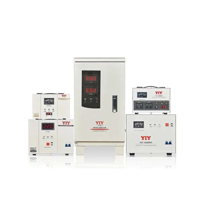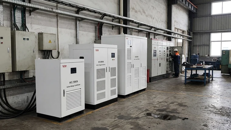
A single phase induction motor usually operates on which power factor? A low, lagging one, especially at light load, because the motor draws magnetizing current. For stabilizer sizing, compare that power factor with running and starting current, voltage range, and kVA before the RFQ.
This guide covers what power factor means for your motor, why a stabilizer doesn’t correct it, how to estimate kVA for a single-phase motor load, and what to check in procurement.
If your project may move from single-phase loads to larger three-phase supply architecture, review YIY’s three-phase stabilizers early instead of assuming one single-phase unit can handle the same starting behavior. For nominal voltage assumptions, you can also check the official IEC 60038 standard voltage guidance, which helps you verify that your voltage references match recognized system-voltage conventions.
Single Phase Induction Motor Usually Operates on Which Power Factor?
You should treat a single-phase induction motor as a lagging-power-factor load unless your measured data proves otherwise. At full load, an induction motor may operate at a much better power factor than it does at no-load or light load, but it still remains an inductive load that demands apparent power from the supply.
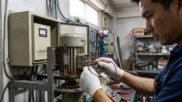
A single-phase induction motor usually operates on a low lagging power factor because its stator draws magnetizing current. That current supports the motor’s magnetic field but does not fully convert into useful shaft output. This is why your supply cable, breaker, contactor, transformer, and voltage stabilizer may carry more current than a simple horsepower-to-watts estimate suggests.
In practice, the power factor is not a fixed value for every motor. Your actual result depends on:
- Motor design and efficiency
- Capacitor-start or capacitor-run arrangement
- Load percentage during operation
- Supply voltage quality
- Starting method
- Pump, fan, compressor, or machine torque requirement
- Ambient heat and duty cycle
This matters most when your motor runs lightly loaded for long periods. A lightly loaded induction motor can still draw magnetizing current, so your useful mechanical output falls faster than your total electrical burden. For you, that means a motor that looks small in kW can still create meaningful kVA demand, heating, and voltage-drop risk.
Why Does Low Lagging Power Factor Affect Stabilizer Sizing?
You should size the stabilizer by apparent power and starting behavior, not by motor horsepower alone. Low power factor increases the kVA your electrical system must support, while starting current can multiply the short-duration load during acceleration.
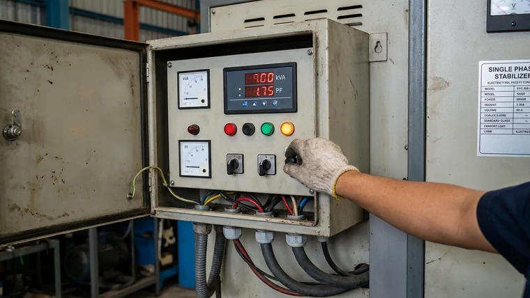
The key relationship is:
kVA = kW ÷ power factor
If your estimated running load is 2.2 kW and the operating power factor is 0.70, the apparent power is:
2.2 ÷ 0.70 = 3.14 kVA
That number does not yet include motor starting current, voltage dips, safety margin, high ambient temperature, or future load expansion. For you, this means a “3 kVA” label may be too close to the edge for a motor application, especially if the motor starts under load.
For a single-phase current estimate, use:
A = kVA × 1000 ÷ V
At 230 V, a 3.14 kVA running demand is about:
3.14 × 1000 ÷ 230 = 13.65 A
This current estimate helps you check whether the cable, plug, breaker, stabilizer winding, bypass path, and contactor are realistic. It is not the final design by itself, because starting current may be several times the running current for a short period.
For motors in the 3 HP class, see the dedicated guide to a stabilizer for 3HP single phase motor. Whatever the size, start with nameplate and measured current: mechanical output (HP × 0.746 kW) is not electrical input, which also depends on efficiency and power factor. Skip efficiency, PF, and inrush and you may undersize the stabilizer.
Can a Voltage Stabilizer Correct the Motor’s Power Factor?
You should not expect a voltage stabilizer to correct power factor by itself. A stabilizer regulates voltage; a capacitor bank or power-factor correction system addresses reactive power.
This distinction protects you from a common specification error. A voltage stabilizer helps keep the motor and control circuit within a safer voltage window during undervoltage, overvoltage, or grid fluctuation. It can reduce weak starts, contactor chatter, nuisance trips, overheating from low voltage, and unstable control behavior. However, it does not remove the motor’s inherent lagging current demand.
| Solution | What it controls | What it does not solve | Where it fits your decision |
|---|---|---|---|
| Servo voltage stabilizer | Output voltage through smooth electromechanical regulation | Does not directly correct lagging power factor | Weak-grid motor loads, workshops, pumps, compressors |
| Relay voltage stabilizer | Step-based voltage correction | Less smooth correction; no true PF correction | Smaller or less sensitive single-phase loads |
| Static / IGBT stabilizer | Fast electronic voltage correction | Does not replace harmonic filtering or PFC | Sensitive loads with fast voltage fluctuation |
| Capacitor bank / PFC panel | Reactive power and power factor | Does not regulate supply voltage by itself | Utility penalty reduction, transformer and cable loading optimization |
| Correctly sized cables and breakers | Current-carrying and protection capacity | Does not stabilize voltage or correct PF | Safe installation and thermal protection |
If your load is small, less sensitive, and cost-constrained, a relay voltage stabilizer may be enough. If your grid voltage drifts for long periods or your motor controls are sensitive, a servo or static solution may be a better fit.
Voltage disturbance tolerance should also be treated as an engineering requirement. The official IEC 61000-4-11 voltage dip and interruption testing page describes testing for voltage dips, short interruptions, and voltage variations. For your project, this means you should ask how the stabilizer and connected equipment behave during real voltage events rather than assuming nominal voltage is always available.
Which Motor and Site Data Should You Compare Before Sizing?
You should compare measured electrical data, not only catalog descriptions. The safest shortlist begins with the motor nameplate, current measurements, starting behavior, voltage log, and installation conditions.
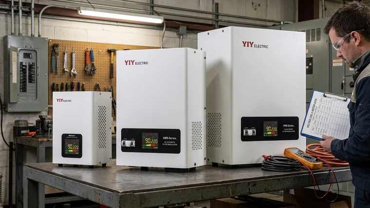
Use this checklist before you compare stabilizer quotations:
| Check | Why it matters | If you skip it |
|---|---|---|
| Motor HP / kW | Establishes the base load | You may size from a vague equipment description |
| Nameplate voltage and frequency | Confirms compatibility with local supply | The stabilizer may not match the motor or site |
| Phase type | Separates single-phase and three-phase architecture | Wrong phase selection can make the system unusable or unsafe |
| Running current | Shows actual current draw | Catalog power may underestimate site demand |
| Starting current | Confirms surge burden during acceleration | Output voltage may collapse during startup |
| Power factor assumption | Converts kW into kVA | Stabilizer, cable, and breaker sizing may be too small |
| Input voltage range | Defines how wide the stabilizer must correct | Regulation may fail under weak-grid conditions |
| Output accuracy | Protects controls, relays, and instruments | Sensitive controls may trip or chatter |
| Duty cycle | Accounts for repeated starts and long operation | Thermal stress may be underestimated |
| Ambient temperature | Affects derating and cooling | Components may overheat |
| Dust and humidity | Drives enclosure and protection choices | Service life may fall in harsh environments |
| Bypass and protection design | Supports maintenance and fault handling | Downtime may increase during service |
| Alarm or event indication | Helps diagnose repeated dips or overloads | Failures may be rediscovered only after downtime |
A practical specification should connect the load list, starting current, power factor, input-voltage window, safety margin, and phase type. If you need a broader framework for that process, use YIY’s industrial voltage stabilizer selection guide as a supporting reference.
For technical numbers, remember what they mean for you:
- kW tells you real power demand.
- kVA tells you what the stabilizer, transformer, cable, and breaker must carry.
- Power factor explains the gap between kW and kVA.
- Starting current explains why a motor can overload a stabilizer briefly even if running current looks acceptable.
- Input-voltage range tells you whether the stabilizer can still regulate under your worst supply condition.
The phrase measurement of 3 phase reactive power using single wattmeter theory belongs to three-phase reactive-power measurement theory. It can help in electrical education or three-phase analysis, but your single-phase motor stabilizer selection still depends on nameplate current, measured running current, starting current, PF assumption, and site voltage behavior.
How Should You Compare Stabilizer Technology for Motor Loads?
You should choose the stabilizer technology according to voltage behavior, load sensitivity, budget, and service conditions. A motor-heavy site with slow voltage drift has different needs from a small appliance load or a fast-fluctuation industrial control panel.
| Technology | Best fit | Main advantage | Practical caution for you |
|---|---|---|---|
| Relay stabilizer | Small loads, household or light commercial use, less sensitive equipment | Cost-effective step correction | Output changes are stepped, so it may not suit sensitive controls |
| Servo stabilizer | Motors, workshops, weak-grid sites, long-duration voltage drift | Smooth voltage regulation and good output accuracy | Requires ventilation, maintenance access, and environmental protection |
| Static / IGBT stabilizer | Sensitive electronics, fast fluctuation, higher-end industrial loads | Fast response and no mechanical correction path | Usually higher cost and more application-specific |
| PFC panel plus stabilizer | Sites with both poor PF and unstable voltage | Addresses both reactive burden and voltage regulation when correctly designed | Requires proper coordination and protection design |
If your site uses pumps, fans, compressors, or machine tools, starting current should be a major selection factor. A stabilizer that handles running current but collapses during startup will still create contactor chatter, low torque, and nuisance tripping.
For three-phase main distribution or larger industrial loads, your next execution step should be a measured-site review. YIY’s 3 phase main line stabilizer sizing guide can help you compare total kVA, phase imbalance, input range, bypass, protection, and installation details.
What Should Your RFQ and Acceptance Review Include?
You should make the RFQ specific enough that two suppliers cannot quote very different systems under the same “motor stabilizer” label. The more clearly you define load, voltage, environment, and protection, the easier it is to compare the technical fit.
Use this acceptance-review structure before purchase approval:
| Check | Why it matters | If you skip it |
|---|---|---|
| Load list attached to RFQ | Forces the quote to match actual equipment | Supplier may quote only from a rough kVA request |
| Motor nameplate photo | Confirms voltage, current, frequency, and phase | Wrong assumptions may enter the design |
| Running-current measurement | Validates real operating load | The stabilizer may be undersized |
| Starting-current estimate or measurement | Captures acceleration demand | Startup sag and trips may continue |
| PF assumption documented | Shows how kW was converted to kVA | Hidden reactive load may overload the system |
| Input-voltage log | Confirms correction range | The stabilizer may not cover your worst grid condition |
| Output accuracy stated | Protects control circuits | Controls may remain unstable |
| Protection functions listed | Confirms overload, delay, bypass, and alarm behavior | Fault handling may be unclear |
| Enclosure and cooling confirmed | Matches dust, humidity, and temperature | Reliability may fall in the real site |
| Wiring diagram supplied | Supports panel integration and maintenance | Installation errors become more likely |
| Test report requested | Provides factory verification | You rely only on brochure claims |
| Warranty and service access reviewed | Reduces downtime after commissioning | Repairs may be slow or difficult |
| Quality system evidence checked | Supports supplier discipline | Procurement proof may be weak |
If the supplier cites quality management, ask for a certificate or audit evidence rather than a logo alone. The official ISO 9001:2015 quality management requirements page gives you the correct standard reference; in your procurement file, verify the certificate scope, issuing body, company name, and validity period.
YIY commonly reviews motor-related stabilizer fit using load list, starting current, input-voltage window, installation environment, and phase architecture. That matters because a single-phase motor in a clean indoor panel and a motor in a dusty, humid, generator-fed workshop are not the same application, even if the HP rating is identical.
What Practical Risks Are You Trying to Avoid?
You are trying to avoid failed starts, hot conductors, nuisance trips, unstable controls, and delayed commissioning. These problems often appear after installation because the original quotation used running watts or horsepower without checking apparent power and starting behavior.
Watch for these warning signs:
- Lights dim when the motor starts
- Pump or compressor starts slowly under low voltage
- Breakers trip during startup but not during running
- Contactors chatter during acceleration
- Stabilizer output fluctuates repeatedly
- Cables, plugs, or terminals feel hot
- Control relays reset during motor cycling
- Generator voltage dips under motor load
If these symptoms already exist, do not only increase the kVA blindly. First verify supply voltage, running current, starting current, PF assumption, feeder length, connection tightness, overload settings, and whether the motor is starting under load. A larger stabilizer may help, but it cannot fix poor wiring, incorrect protection settings, or mechanical overload by itself.
Frequently Asked Questions
How Does a 3 Phase Servo Motor Work?
A three-phase servo motor uses controlled three-phase current and feedback to regulate torque, speed, and position. You should not confuse it with a servo voltage stabilizer, where a servo mechanism adjusts transformer output voltage. For verification, check the motor nameplate, drive manual, encoder or resolver feedback requirement, supply voltage, and wiring diagram.
Are All Servo Motors 3-Phase?
No. Servo motors may be single-phase AC, three-phase AC, DC, or brushless designs depending on the drive and application. Before procurement, you should verify the motor nameplate, drive manual, phase requirement, supply voltage, and control wiring. This prevents you from matching the wrong stabilizer or breaker to the actual equipment.
How Do You Balance a 3-Phase System?
You balance a three-phase system by distributing loads evenly and measuring line currents, line-to-line voltages, and neutral current where applicable. Before sizing a three-phase stabilizer, record current on each phase under normal operating conditions and identify any phase that carries much more load than the others. If the imbalance comes from uneven single-phase loads, rebalance those loads first.
How Do You Stabilize 3 Phase Power?
You stabilize three-phase power with a correctly sized three-phase voltage stabilizer matched to total kVA, starting current, voltage range, phase imbalance, bypass design, and protection requirements. Your verification action is to compare the stabilizer quotation against a site voltage log, load list, phase-current measurements, and startup conditions before approval.
What Are the Disadvantages of a Servo Motor or Servo-Type Stabilizer?
Servo systems can cost more and require more careful installation, ventilation, maintenance access, and environmental protection than simpler relay-based options. In dusty, humid, or hot locations, you should check cabinet sealing, cooling paths, moving parts, control boards, wiring access, warranty terms, and service instructions before purchase.
Final Procurement Step
You should finish with a short technical review before you ask for a final price. Compare voltage, phase, kVA, PF assumption, inrush margin, input range, enclosure, ambient temperature, protection functions, wiring diagram, test report, and warranty terms in one line-by-line checklist.
If you are moving toward a larger purchase, this compare before buying a voltage stabilizer guide can support your final review process without replacing the motor-specific calculations above.
A low-friction next step is to send YIY your load list, motor nameplate, starting-current estimate, input-voltage window, and installation conditions for a first-pass sizing review. You do not need perfect logs to begin; you only need enough information to identify whether the stabilizer capacity, phase type, and regulation technology are directionally correct before the RFQ becomes a purchase order.