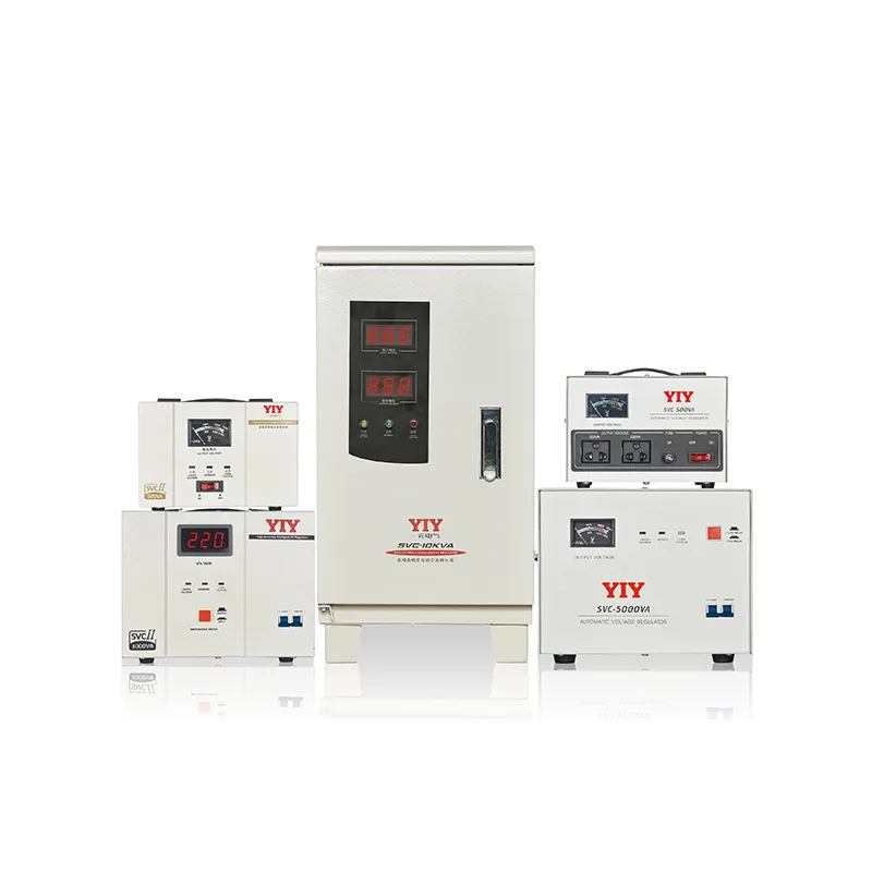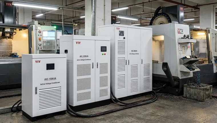
Voltage fluctuations aren’t just a nuisance for sensitive industrial loads; they translate directly into unplanned downtime, accelerated equipment wear, and costly production halts. When grid instability threatens critical CNC machinery or automated test benches, selecting a servo stabilizer controller becomes a high-stakes procurement decision. A properly engineered servo voltage stabilizer bridges the gap between cheaper relay switches and premium static IGBT systems, consistently delivering ±0.5% to ±3% output precision with sub-two-second response times. It provides the rugged reliability and continuous stepless correction that modern production floors demand.
Choosing the correct topology requires more than matching headline kVA ratings. This technical guide breaks down the internal regulation mechanics, compares performance trade-offs against competing voltage stabilizer controller architectures, outlines the environmental and electrical checkpoints you must verify before procurement, and maps long-term maintenance requirements to your specific load profiles. Use this framework to bypass vendor speculation and align your industrial power protection budget with actual operational risk.
How Servo Stabilizer Controllers Regulate Voltage
The core advantage of servo-based power conditioning lies in its electromechanical feedback loop, which replaces discrete voltage steps with seamless, continuous adjustment. Unlike static switching architectures that introduce micro-transients during tap changes, this system operates as a tightly coupled closed control loop. It dynamically compensates for grid instability while preserving waveform integrity across the entire regulation window.
MCU-Driven Closed-Loop Correction
At the hardware level, an industrial-grade microcontroller unit executes continuous A/D sampling of the incoming supply voltage. By comparing the instantaneous line value against a calibrated reference setpoint, the processor calculates the exact amplitude correction required. This real-time MCU voltage regulation drives a proportional control output that commands the correction mechanism, effectively closing the feedback loop before grid sag or swell conditions can propagate downstream to critical loads. The underlying principles mirror established servo control mechanism architectures, utilizing high-refresh rate position feedback to maintain target voltage despite rapid line disturbances.
Stepless Toroidal Ratio Adjustment
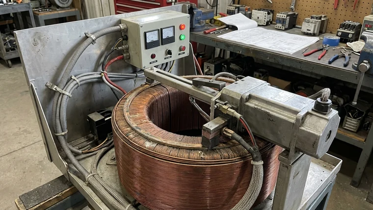
The control signal directly actuates a high-torque servo motor tasked with positioning a carbon brush along the active windings of a toroidal autotransformer. As the brush traverses the exposed coil surface, it continuously varies the turns ratio, providing linear voltage scaling without interrupting the electrical path. Continuous mechanical motion replaces abrupt relay switching, extending brush life while maintaining optimal electrical contact pressure under varying environmental conditions. This stepless mechanical interpolation eliminates contactor bounce and ensures a smooth transition across the entire operational input range.
Precision Metrics for Demanding Environments
By combining high-speed digital sampling with direct mechanical actuation, this architecture maintains an output precision of ±0.5% to ±3% under highly dynamic loading conditions. Facilities operating multi-axis servo stabilizer for CNC machines, high-resolution medical imaging suites, and precision automated test equipment depend on this predictable voltage profile. The system achieves typical correction response times of 1–2 seconds, a performance bracket specifically engineered for load environments that demand stepless regulation. This topology aligns with stringent compliance standards, effectively preventing control board resets, safeguarding delicate instrumentation from cumulative insulation stress, and eliminating the micro-voltage flickers that degrade sensitive automation workloads.
Servo vs. Relay vs. IGBT: Topology Trade-offs
Selecting a voltage regulation topology requires matching correction behavior to your specific load profile and lifecycle budget. The motor-driven architecture isn’t the absolute fastest or most mathematically precise, but it consistently delivers the lowest total cost of ownership for dynamic industrial environments.
| Topology | Correction Mechanism | Output Precision | Response Time | Maintenance Profile | Ideal Use Case |
|---|---|---|---|---|---|
| Relay | Electromechanical tap switching (stepped) | ±4% to ±8% | < 20ms (per step) | High: Frequent contactor replacement, arc degradation | Non-critical auxiliary loads, lighting, HVAC |
| IGBT (Static) | High-frequency semiconductor synthesis (stepless) | ±0.5% to ±1% | 1–20 ms (sub-cycle) | Low to Moderate: Thermal management, firmware diagnostics | Semiconductor fabs, metrology, zero-tolerance IT |
| Servo | Motor-driven carbon brush on autotransformer (stepless) | ±0.5% to ±3% | 1–2 seconds | Moderate: Scheduled brush/winding inspection, lubrication | Mixed industrial loads, CNC, medical, production lines |
Relay Systems: Fast Switching, Mechanical Wear
A traditional relay voltage stabilizer delivers rapid step responses by instantly jumping across fixed transformer taps using electromechanical contactors. This architecture suits auxiliary circuits where brief voltage flickers remain operationally acceptable. However, discrete stepping inherently caps regulation accuracy, while repeated contact arcing degrades copper surfaces and forces frequent hardware swaps, disrupting long-term uptime.
IGBT Systems: Sub-Cycle Accuracy, High Complexity
Static IGBT topologies remove rotating components entirely, utilizing high-frequency semiconductor switching to synthesize exact compensation voltages without interrupting downstream power paths. These designs achieve laboratory-grade precision while reacting in single-digit milliseconds. Procuring them requires navigating steep capital costs, advanced thermal management requirements, and complex firmware dependencies that demand specialized troubleshooting personnel.
Servo Stabilizer Controller: Optimal Balance for Mixed Loads
Servo designs harmonize continuous mechanical interpolation with high-speed digital sampling to eliminate the abrupt voltage transitions typically found in contactor-based systems. For detailed technical breakdowns on phase-specific configurations, our comprehensive relay vs servo vs IGBT comparison outlines exact phase-matching criteria. Stepless voltage scaling prevents harmful micro-transients that routinely stress mixed or heavily inductive machinery like large compressor banks. Controlled carbon brush traversal maintains steady electrical contact pressure across the toroidal winding, drastically reducing arc-induced thermal fatigue and extending scheduled maintenance intervals.
Specification and Site-Condition Checkpoints
Procurement frequently stalls when buyers fixate on headline kVA ratings while ignoring the hidden electrical variables that dictate real-world uptime and long-term service overhead. Aligning your servo stabilizer controller with precise site conditions prevents premature component fatigue and eliminates costly operational blind spots.
Grid Compliance and Load Dynamics
Always validate the unit’s accepted input voltage tolerance against your utility’s recorded daily swing, rather than relying solely on nominal nameplate specifications. A compliant architecture must align strictly with IEC 60038 standard voltages, comfortably accommodating ±10% to ±20% baseline deviations without triggering nuisance shutdowns or reducing correction accuracy.
Concurrently, map your facility’s dominant load architecture against the controller’s actual surge handling bandwidth. Heavy inductive motors generate severe startup transients that rapidly exhaust narrow regulation windows, while non-linear variable frequency drives inject harmonic pollution that severely compromises true power factor. When determining how to size a servo stabilizer, sizing your unit 15% above calculated peak demand safely absorbs these mechanical spikes and prevents transformer saturation.
Bypass Redundancy and Lifecycle Maintenance
Your selected bypass configuration directly dictates production vulnerability during routine calibration or unexpected internal controller faults. Specify an automatic transfer switch that instantly bridges unregulated grid power during critical maintenance windows, or integrate a manual breaker if safety protocols mandate strict isolation during troubleshooting.
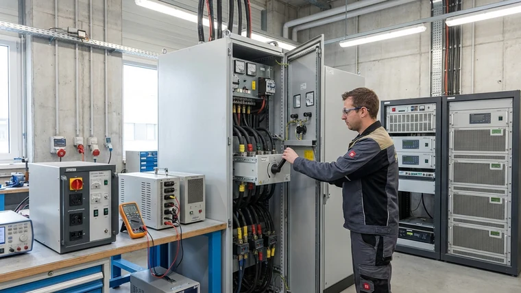
Electromechanical voltage regulation relies on predictable physical contact that demands disciplined inspection intervals and proactive thermal monitoring. Procurement contracts should explicitly mandate carbon brush and winding inspection schedules, requiring contact surface evaluations every 10,000 to 12,000 operating hours. Partnering with manufacturers who guarantee OEM spare part inventories ensures predictable lifecycle servicing costs. For a broader view of topology maintenance expectations, the stabilizer voltage regulator guide details exact servicing intervals across all major architectures. Direct access to genuine replacement brush assemblies and certified control board diagnostics allows technicians to perform rapid repairs without relying on expensive third-party contractors.
Matching Topology to Application Scale and Long-Term Service Needs
Selecting the right voltage regulation architecture requires aligning facility capacity demands with proven engineering bandwidth. Industrial environments rarely operate on static loads, so stabilizers must handle wide kVA fluctuations without compromising response times. Proper sizing bridges the gap between initial capital expenditure and long-term operational stability.
Capacity Alignment and Quality Benchmarks
A robust specification begins by mapping peak demand to a precise capacity bracket, typically spanning 0.5 kVA to 3000 kVA across modern industrial ranges. Right-sizing at this stage prevents thermal overload in transformer windings while eliminating idle overspending. Beyond raw power ratings, procurement teams must treat ISO 9001 and ISO 14001 certified designs alongside CE compliance as non-negotiable baseline criteria. These manufacturing standards guarantee rigorous quality control, traceable supply chains, and environmental safeguards that directly reduce long-term failure rates.
Global Sourcing Versus Regional Constraints
Supply chain resilience hinges on whether your vendor operates globally or relies on a narrow domestic footprint. Regionally constrained manufacturers frequently struggle with complex export logistics, whereas established exporters streamline deliveries across 130+ countries with localized support networks. YIY differentiates itself by maintaining a complete topology portfolio—covering relay, servo, and IGBT architectures—paired with comprehensive OEM/ODM capabilities. This operational flexibility allows engineering teams to specify exact enclosure ratings or custom control interfaces without waiting for standard catalog refreshes.
Preparing for the Engineering Review
Final model selection must transcend generic catalog browsing and standard sizing charts. Procurement professionals should treat the quotation phase as a collaborative engineering exercise rather than a simple transactional order.
Begin by preparing a granular load audit that records startup surge currents and harmonic distortion across critical assets. Pair this analysis with a verified site single-line diagram to clearly identify upstream protective boundaries and critical branch circuits. Always include a historical grid profile capturing daily voltage swings and transient fault patterns. Submitting this technical documentation streamlines the engineering handoff, enabling YIY specialists to validate topology requirements and finalize a maintenance-ready configuration tailored to your exact operational context.
Frequently Asked Questions
What should buyers evaluate before choosing a servo stabilizer controller?
Look beyond headline kVA ratings and verify input voltage tolerance, load architecture, and maintenance accessibility. Ensure compliance with international grid standards to accommodate daily swings, which prevents nuisance shutdowns during peak operational hours. Map inductive startup currents and confirm surge capacity. Specify an automatic bypass switch for maintenance, and verify the manufacturer stocks genuine carbon brush assemblies for predictable service costs.
When is a servo stabilizer controller necessary?
Motor-driven regulation is essential when sensitive or heavily inductive loads cannot tolerate discrete voltage steps. Facilities running CNC machines or automated test equipment will experience damaging micro-transients from cheaper relay switches. Deploy a servo design when you need ±1% to ±3% precision with sub-two-second correction, balancing mechanical reliability against static IGBT complexity. This topology eliminates contactor bounce and extends scheduled maintenance intervals for high-uptime environments.
How should a servo stabilizer controller be sized or specified?
Begin with a granular load audit tracking continuous demand and peak startup surges. Size the unit at 15% above calculated peak demand to absorb mechanical spikes and prevent thermal stress. Select an MCU-driven topology with continuous toroidal adjustment. Always submit your site single-line diagram during procurement to align the stabilizer circuit with upstream protective boundaries. Pair this data with verified thermal monitoring protocols to ensure long-term winding longevity.
Final Thoughts
Selecting the right voltage regulation architecture ultimately comes down to aligning correction behavior with your actual operational risk profile. While relay systems offer speed at the cost of precision, and static IGBT topologies deliver sub-cycle accuracy with steep capital overhead, the servo stabilizer controller consistently provides the most resilient balance for mixed industrial environments. Its stepless mechanical interpolation eliminates harmful micro-transients, protecting variable inductive machinery while maintaining ±1% to ±3% output tolerance.
Before finalizing any procurement order, run your load audit against the site compliance checklist: verify historical grid swings, size the unit with a 15% surge margin for startup transients, and align maintenance contracts with realistic carbon brush replacement intervals. The engineering is proven, but misapplying topology to your specific duty cycle guarantees unnecessary downtime or inflated CAPEX.
Do not leave voltage protection to catalog browsing. Compile your facility’s single-line diagram, measured harmonic profiles, and peak surge data, then request a YIY engineering review. Our specialists will validate whether servo, relay, or IGBT topology delivers the lowest total cost of ownership for your exact application, securing a reliable power baseline before capital is committed.
About YIY
Zhejiang Yiyen Holding Group Co., Ltd. (YIY) is a professional voltage stabilizer manufacturer with 16+ years of experience. With a 30,000 sqm modern facility and an annual production capacity of 1,000,000+ units, our products are exported to 130+ countries. We provide OEM/ODM customization services and are ISO 9001:2015 certified, committed to delivering stable and reliable voltage protection solutions to global customers.
Contact Us
Email: yiyen at yiyen.com
Phone/WhatsApp: +86 13587452904
Website: https://www.yiyavr.com/
Related reading: Servo Voltage Stabilizer — Overview.