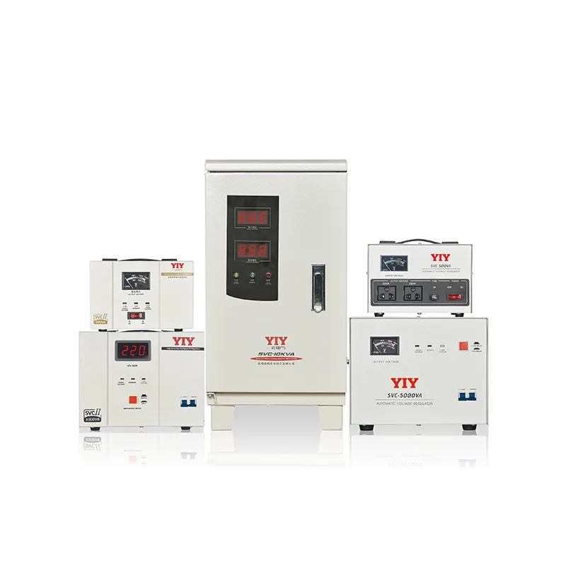
Choosing the wrong voltage regulation topology directly compromises sensitive industrial equipment and inflates maintenance overhead. Engineers and procurement teams face a critical tradeoff: accepting the step-wise response and limited accuracy of conventional relay units, or investing in continuous motor-driven correction. When evaluating a servo stabilizer vs normal stabilizer, the decision hinges on whether your operational workflow tolerates wider grid swings or demands tighter, IEC-aligned precision.
This guide maps the engineering realities behind that choice. We break down how each architecture responds to supply variances, match control methods to specific load profiles, and detail the essential compliance and sizing criteria before procurement. By aligning your infrastructure strategy with verified performance metrics, you can guarantee equipment uptime while optimizing total cost of ownership.
Understanding the Core Difference: Servo vs. Normal Stabilizers
The fundamental technical split between these voltage regulation systems lies entirely in their correction methodology. Normal stabilizers utilize electromagnetic relays that switch transformer taps in discrete, stepped increments, often generating brief transitional micro-spikes during heavy grid fluctuations. Servo configurations replace this binary switching logic with a closed-loop DC motor that continuously adjusts a carbon brush across a variable autotransformer, delivering seamless, real-time voltage smoothing without the abrupt current spikes that degrade conventional relay architectures.
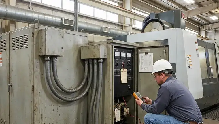
For plant engineers and maintenance managers, the topology selection directly dictates downstream equipment longevity and mean time between failures. Sensitive automation environments cannot safely absorb the ±5% to ±8% voltage variance typical of stepped regulation, making the ±0.5% accuracy of motor-driven correction a strict operational requirement. Procurement specialists must then validate these technical premiums against strict facility budgets, carefully balancing the lower entry costs of relay architectures against the significantly reduced lifecycle maintenance overhead of servo-driven units, all while ensuring compliance with globally recognized benchmarks like the IEC 60038 standard voltages.
Operational Trade-off Matrix
Evaluating these topologies requires mapping specific load characteristics against documented grid instability patterns. Relay-based systems remain optimal for environments experiencing gradual, predictable voltage drift where millisecond switching delays pose zero threat to downstream logic boards. Servo architectures become strictly non-negotiable when managing highly reactive inductive loads or regions plagued by rapid, high-amplitude power surges.
Single-Vendor Flexibility
Modern industrial facilities rarely demand uniform voltage regulation across every operational zone, making topology diversification highly strategic. Sourcing from a manufacturer that integrates relay, servo, and IGBT stabilizers under a single corporate roof eliminates the administrative friction of qualifying multiple vendors during phased infrastructure expansions. Technical teams can deploy economical relay banks for general workshop lighting and HVAC auxiliary circuits, while routing precision-sensitive CNC or automated robotics through dedicated, continuously-correcting servo channels.
This unified procurement pathway standardizes ISO compliance documentation, consolidates critical spare parts inventories, and guarantees seamless capacity scaling without disrupting established vendor relationships. When evaluating long-term capital planning, the engineering decision naturally shifts from isolated unit pricing to a cohesive, application-specific power resilience strategy that adapts to evolving load profiles.
How Servo Voltage Regulation Works in Industrial Environments
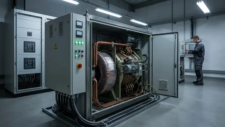
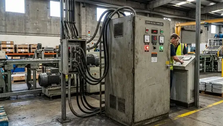
Industrial deployment of a servo voltage stabilizer operates on a continuous closed-loop control architecture that fundamentally differs from stepped electromagnetic relay systems. A brushless DC motor continuously monitors the secondary winding output through a high-speed sampling circuit, then precisely repositions a contact arm across a toroidal autotransformer. Understanding the difference between mainline and servo stabilizers is critical here, as industry analyses confirm that motor-driven architectures fundamentally rely on proportional tracking rather than discrete tap-jumping. This mechanical translation dynamically adjusts the transformation ratio in real time, neutralizing severe grid sags and transient harmonics before they penetrate critical factory infrastructure while maintaining stable phase balance across fluctuating networks.
The Brushless Autotransformer Feedback Loop
The core correction engine relies on proportionate voltage tracking rather than binary tap switching. When supply conditions deteriorate due to heavy inductive motor startups or regional brownouts, the control board instantly calculates the differential and commands micro-adjustments to the carbon brush assembly. Because the actuator moves only the exact distance required to restore nominal voltage, the system eliminates contact arcing and thermal hotspots while delivering uninterrupted power flow in electrically noisy or vibration-heavy manufacturing floors.
Precision Metrics Versus Conventional Limits
The operational superiority translates directly into documented performance thresholds, where certified servo units consistently guarantee an output accuracy of ±0.5% to ±3% while executing full voltage corrections within ≤1‑2 seconds. Normal relay stabilizers, constrained by discrete step increments, inherently operate within a ±5% to ±8% tolerance window and require significantly longer settling times that frequently trigger protective fault shutdowns. Deploying servo-driven regulation in sensitive manufacturing environments justifies the initial capital expenditure by preventing PLC nuisance tripping, reducing insulation breakdown, and ensuring strict compliance with modern automation power standards.
Why Harsh Grids Demand Continuous Correction
Facilities relying on aging utility infrastructure or operating in regions with frequent load shedding face unpredictable voltage profiles that degrade over time. Servo topology bridges this infrastructure gap by continuously compensating for minute fluctuations, protecting sensitive automation assets without requiring manual tap adjustments or complex static converters.
When to Choose Servo Over Relay or Static Topologies
Selecting the correct voltage regulation architecture depends entirely on your facility’s load tolerance thresholds and operational continuity requirements. The topology decision is not merely a capital procurement exercise; it dictates downstream equipment resilience and maintenance bandwidth. Engineers must map specific application profiles to the inherent correction speeds, harmonic sensitivity, and lifecycle demands of each stabilization method.
Application Mapping for Continuous Regulation
Highly reactive inductive loads and precision-dependent manufacturing equipment demand seamless, uninterrupted power conditioning. CNC machining centers, digital medical imaging arrays, and synchronized automated assembly lines generate rapid current transients that step-based relays simply cannot track fast enough. Servo stabilizers excel here by employing a proportional tracking motor that continuously sweeps the autotransformer windings, neutralizing severe grid sags without introducing the transition spikes that nuisance-trip sensitive PLC logic boards.
Lifecycle Maintenance Realities
Each stabilization topology carries distinct operational overhead profiles that directly impact long-term facility management budgets. As detailed in our comprehensive relay vs servo vs IGBT guide, conventional relay systems rely on mechanical contactors that suffer accelerated degradation from repetitive electrical arcing during heavy grid swings, eventually demanding premature component swaps. Static IGBT configurations eliminate physical wear but require aggressive active cooling and dedicated ventilation channels to manage continuous switching heat losses. Servo-driven units introduce controlled mechanical friction in the carbon brush interface, yet this wear remains predictable, easily monitored during standard PM schedules, and rarely triggers unplanned production shutdowns.
Defining the Cost-to-Precision ROI
Servo configurations capture the optimal sweet spot when production workflows mandate tight ±0.5% to ±2% output tolerance without justifying the extreme capital expenditure of fully static power converters. They deliver maximum ROI in mid-capacity installations where voltage consistency directly correlates with yield rates and sensitive asset lifespan. Conversely, standard relay or main-line magnetic designs remain strictly appropriate for non-critical auxiliary infrastructure. Protecting general lighting circuits, heavy-duty HVAC compressors, and basic motor starters with stepped regulation keeps initial CapEx low, as these rugged downstream assets safely absorb the ±5% to ±8% variance bands inherent to cheaper discrete architectures.
| Feature | Normal (Relay) Stabilizer | Servo Motor Stabilizer | Static (IGBT) Stabilizer |
|---|---|---|---|
| Regulation Method | Stepped electromechanical switching | Continuous carbon brush & motor control | Solid-state semiconductor switching |
| Output Accuracy | ±5% to ±8% | ±0.5% to ±3% | ±0.1% to ±0.5% |
| Response Time | 50ms – 1s per step | ≤1–2 seconds (continuous) | ≤0.02 seconds (instantaneous) |
| Wear & Maintenance | Contact arcing, relay fatigue | Predictable brush wear, routine lubrication | Thermal management, cooling fans |
| Ideal Load Profile | Resistive loads, HVAC, lighting, basic motors | CNC, medical imaging, PLCs, automation | Semiconductor fab, data centers, MRI |
| Cost Tier | Entry-level (Lowest) | Mid-range (Optimal ROI) | Premium (Highest) |
Specification and Maintenance Checkpoints Before Buying
Finalizing a servo stabilizer purchase requires validating the unit against your actual grid profile and downstream load characteristics before procurement approvals. Before committing to a configuration, reviewing baseline 20kva voltage stabilizer specifications provides a reliable engineering baseline for mapping actual grid profiles and peak inrush demands against your facility’s capacity needs. Skipping these engineering checkpoints inevitably leads to chronic undersizing, nuisance tripping, and accelerated component degradation across critical production lines.
Critical Technical Validation Points
Map the facility’s exact input voltage band against the unit’s rated correction window to prevent the servo motor from operating in continuous high-duty cycles. Always calculate peak inrush currents for reactive loads like VFDs and apply a 15–20% safety margin above your maximum load to accommodate future expansions. Mandate an integrated automatic bypass circuit to maintain uninterrupted operations during routine maintenance, while factoring ambient site conditions directly into your thermal budget to dictate mandatory IP enclosures and forced cooling.
Mitigating Operational Risks Through Certified Design
Substandard assemblies frequently exhibit terminal overheating and chronic voltage hunting, a control loop instability that oscillates endlessly around nominal setpoints and rapidly degrades sensitive PLC I/O modules. Manufacturing under strict ISO 9001 and ISO 14001 certifications systematically eliminates these operational risks through rigid thermal stress testing, calibrated winding processes, and fully traceable component sourcing. Verified carbon brush contact pressure and standardized autotransformer insulation classes prevent electrical arcing, delivering the continuous correction stability required by high-speed automated networks.
Commercial and Lifecycle Verification
Explicitly define the full warranty scope during technical negotiations, carefully documenting standard exclusions for routine carbon brush replacement and control board micro-processor failures. Secure written commitments for critical spare part availability across a minimum ten-year service horizon to eliminate procurement delays and extended production downtime. Validate remote monitoring architecture before signing the final quotation, ensuring native Modbus protocols integrate seamlessly with your existing facility management systems without requiring expensive third-party hardware gateways.
Scaling Voltage Protection with Manufacturer Expertise
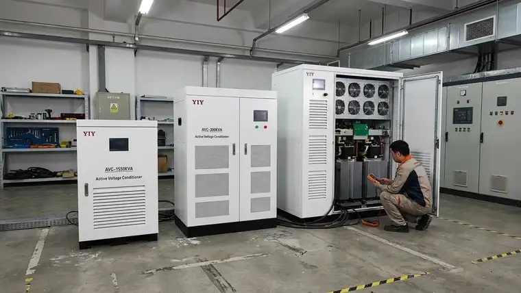
Translating theoretical topology advantages into long-term operational resilience requires a manufacturing partner capable of scaling engineering precision globally. YIY’s dedicated production infrastructure spans a comprehensive 0.5 KVA to 100+ KVA servo stabilizer range, specifically engineered to support diverse load architectures across heavy manufacturing and commercial utility facilities. This broad capacity portfolio, actively deployed and field-validated across 130+ countries, ensures that localized grid anomalies never dictate your critical equipment reliability or downstream automation uptime.
Site-Specific Engineering Over Standardized Catalogs
Off-the-shelf voltage regulation units frequently degrade under unique environmental stressors or unconventional phase balancing requirements common in aging utility infrastructure. Our engineering teams align custom transformer winding geometries, exact enclosure IP ratings, and flexible single-to-three phase configurations directly with rigorous on-site power audits and continuous load logging. Whether your facility demands IP54 particulate shielding for aggressive machining environments or specialized forced-air thermal dissipation for enclosed switchrooms, site-driven customization systematically eliminates the contact fatigue inherent in generic deployments.
Shifting Procurement from Price to Topology Validation
Standard procurement workflows frequently stall on isolated unit pricing long before validating the fundamental correction architecture required for continuous voltage regulation. True lifecycle cost optimization begins with topology confirmation derived from actual harmonic load profiles, inductive reactive kickbacks, and historical grid fluctuation analysis. By cross-referencing your facility’s peak operational demands against our documented thermal and correction matrices, technical buyers secure precise regulation without capitalizing on severely over-engineered specifications that waste capital expenditure and compromise thermal efficiency.
Finalize your power protection strategy through a structured, data-driven technical handoff rather than relying on static product catalogs. Request a comprehensive grid analysis review that maps your exact operational parameters directly to the optimal stabilization topology and integrated bypass architecture. Our engineering division evaluates peak inrush transients, physical spatial constraints, and regional IEC compliance mandates before delivering a rigorously validated configuration tailored to your specific predictive maintenance workflows.
Frequently Asked Questions
What should buyers evaluate before choosing servo stabilizer vs normal stabilizer?
Focus on downstream load sensitivity and real-world grid stability patterns. Servo topologies protect CNC systems or automated robotics that cannot tolerate the ±5% to ±8% output variance of traditional relay switching. Normal stabilizers remain optimal for auxiliary infrastructure like HVAC compressors and general lighting. Always cross-reference acceptable equipment downtime, long-term maintenance bandwidth, and required precision thresholds before finalizing procurement approvals.
When is servo stabilizer vs normal stabilizer necessary?
Deploy a servo-driven architecture when your facility faces rapid voltage sags, frequent brownouts, or highly reactive inductive loads that routinely trigger nuisance tripping. The continuous motor-driven feedback loop guarantees ±0.5% to ±3% output accuracy within two seconds, completely eliminating the transitional micro-spikes that degrade PLC logic boards. Conversely, if your regional grid only experiences gradual voltage drift, standard relay units provide adequate protection at a significantly lower entry cost.
How should servo stabilizer vs normal stabilizer be sized or specified?
Base your capacity calculations on total running kilovolt-amperes plus a mandatory 15–20% engineering safety margin to safely absorb heavy inductive startup surges. Map peak grid fluctuations directly against the stabilizer’s rated correction window to prevent continuous mechanical cycling and thermal fatigue. Specify an integrated automatic bypass for production continuity during scheduled maintenance, and validate enclosure IP ratings against ambient plant-floor dust or humidity levels.
Final Thoughts
Selecting between servo and normal stabilizers ultimately hinges on aligning voltage correction methodology with your facility’s true operational tolerance. Correctly mapping topology to specific load requirements eliminates preventable equipment stress and safeguards production schedules against costly, unplanned downtime. The engineering tradeoff remains decisive: deploy continuous servo correction where tight accuracy dictates machine yield, and step down to economical relay architectures only when downstream assets safely tolerate gradual grid drift. This targeted approach guarantees optimal TCO without over-engineering or risking critical control faults. Do not finalize capital allocation on generic catalogs. Initiate a technical application review with our engineering team to validate your exact grid profile, peak inrush demands, and IEC compliance parameters before specifying your voltage protection strategy.
About YIY
Zhejiang Yiyen Holding Group Co., Ltd. (YIY) is a professional voltage stabilizer manufacturer with 16+ years of experience. With a 30,000sqm modern facility and an annual production capacity of 1,000,000+ units, our products are exported to 130+ countries. We provide OEM/ODM customization services and are ISO 9001:2015 certified, committed to delivering stable and reliable voltage protection solutions to global customers.
Contact Us
Email: yiyen@yiyen.com
Phone/WhatsApp: +86 13587452904
Website: https://www.yiyavr.com/
If you found this article helpful, contact us for a sizing review or customized solution.