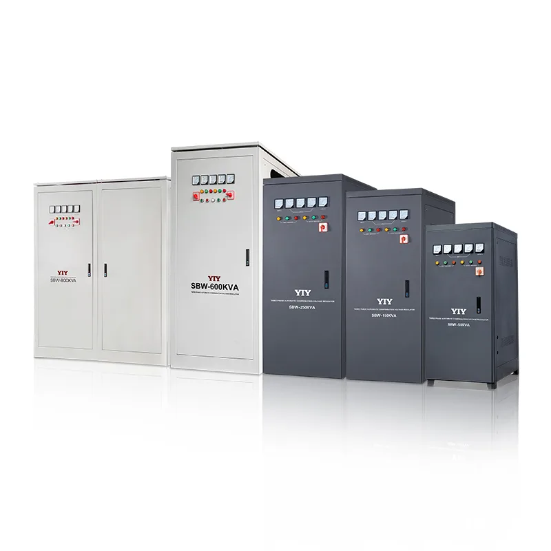
At 200 KVA and above, the voltage stabilizer stops being a piece of equipment and becomes a piece of infrastructure. It shares a category with transformers, switchgear, and generator sets — assets that define the electrical backbone of a facility for ten to fifteen years. A wrong specification at this scale does not trip a breaker; it shuts down a production floor. A single unplanned outage at a CNC machining plant or an injection molding facility routinely costs more than the stabilizer itself in lost output, rejected batches, and emergency restart labor.
This guide is written for the people who carry that risk: facility managers, large-factory procurement teams, and EPC contractors responsible for specifying power-quality infrastructure on industrial and commercial projects. It covers capacity planning for 200-500 KVA loads, technology selection between oil-cooled servo, dry servo, and IGBT active voltage conditioning, total cost of ownership analysis across a ten-year service life, and installation requirements specific to units that weigh over half a ton and draw 300+ amps per phase.
When You Need 200+ KVA
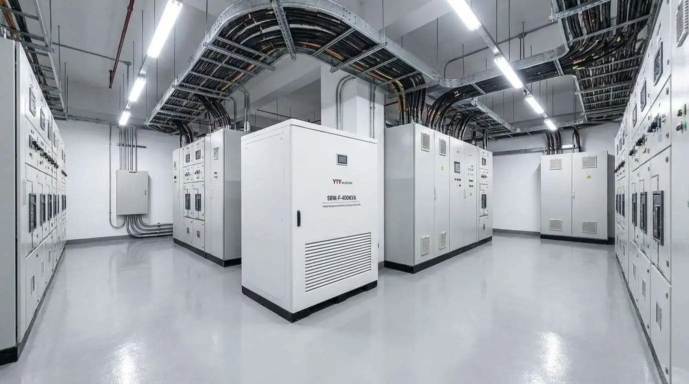
The 200 KVA threshold is not arbitrary. It is the capacity boundary where three factors converge: the load mix becomes motor-dominated, the installation becomes a civil-structural project (concrete pads, oil containment, dedicated ventilation), and the consequences of a specification error shift from inconvenient to financially material.
Decision tree — what pushes a facility past 100 KVA:
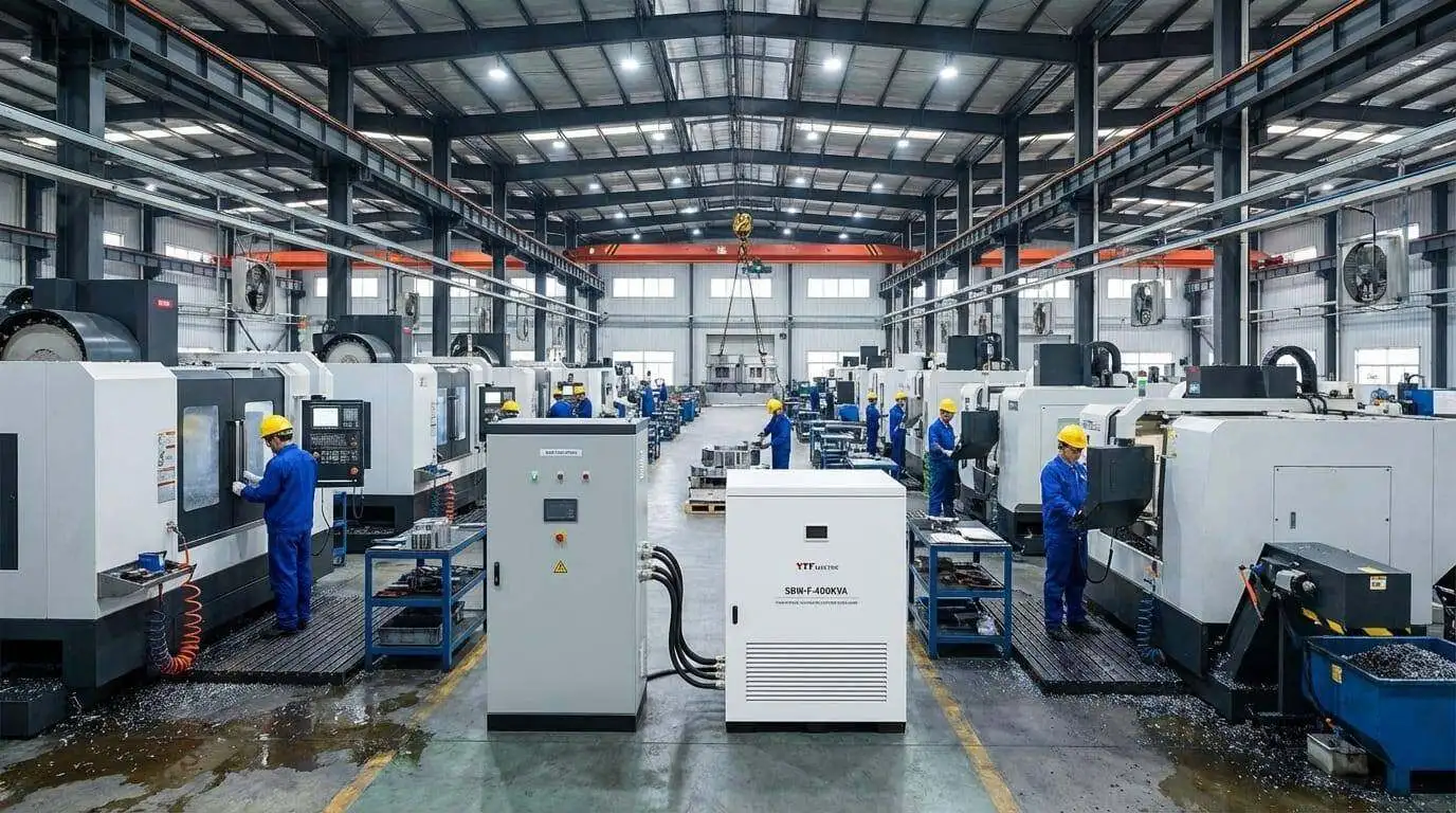
- Motor-dense production floors. A single CNC machining center with a 15 kW spindle and servo axes draws 8-10 KVA after inrush correction. Ten machines on one feeder, plus coolant systems, lighting, and compressed air, cross 200 KVA before the second shift starts.
- Injection molding plants. Hydraulic injection units pull 50-100 KVA each. Two to four machines on a shared bus exceed 200 KVA at steady state, and motor starting transients push instantaneous demand far higher.
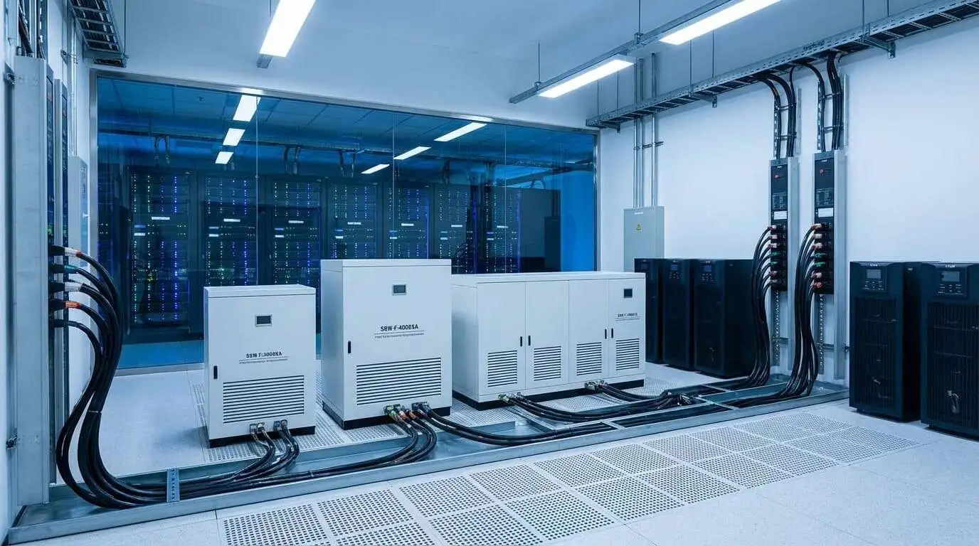
- Data center feeders. A single server rack row consumes 20-40 kW. The UPS input stabilizer for a mid-size data hall starts at 200-300 KVA.
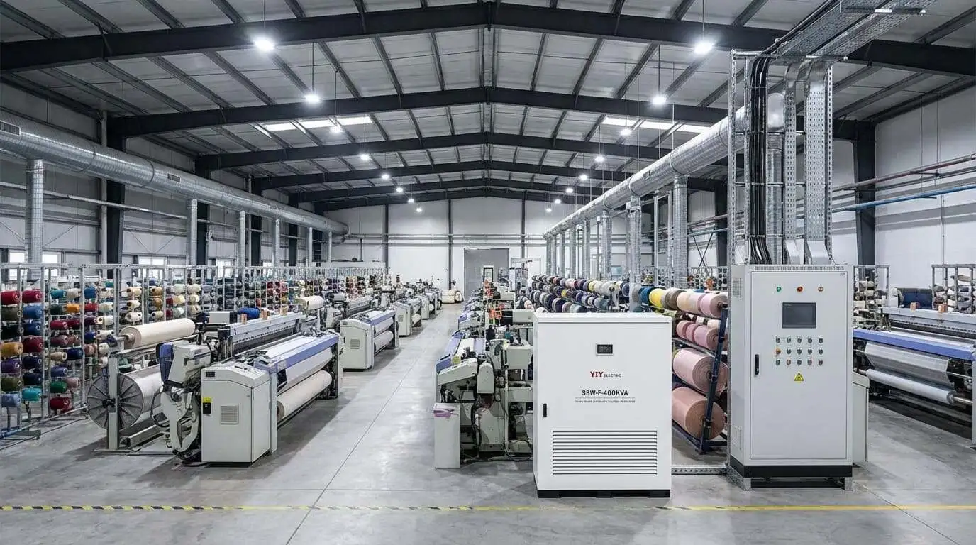
- Textile mills. Spinning and weaving frames are constant-torque motor loads running three shifts. A single production hall often requires 300-500 KVA of voltage regulation.
- Commercial building mains. A mid-rise office tower or hospital wing with central HVAC, elevators, and lighting banks frequently lands in the 200-500 KVA regulation band.
The real-power translation at 0.8 power factor:
| Stabilizer Rating | Real Power at PF 0.8 | Typical Facility |
|---|---|---|
| 200 KVA | ~160 kW | Small CNC production floor, medium data center feeder |
| 300 KVA | ~240 kW | Injection molding plant, textile spinning hall |
| 500 KVA | ~400 kW | Large factory main, commercial building mains |
If the total connected load crosses 130 kW of real power with a motor-dominant mix, the conversation moves to this capacity band.
200 vs 300 vs 500 KVA — Capacity Planning
The sizing formula is the same one used for smaller units, but the safety margin is different and the configuration decisions are more consequential.
Required KVA = Total Load (kW) / Power Factor x Safety MarginThe critical difference at this scale: motor-heavy loads need a 2-3x safety factor, not 1.25. A 200 KVA facility where 70% of the load is induction motors (CNC spindles, compressors, conveyor drives) will pull 400-600 KVA of apparent power during a coordinated startup sequence. The 1.25 margin that works for office equipment will trip the stabilizer on overload during the first morning shift change.
Rule of thumb for motor-heavy industrial: Apply 2-3x multiplier to the motor portion of the connected load, then add the non-motor portion at face value.
Example: A production floor with 120 kW of motor loads and 30 kW of controls, lighting, and HVAC electronics:
Motor portion:   120 kW / 0.8 PF x 2.5 (inrush factor) = 375 KVA
Non-motor:       30 kW / 0.8 PF x 1.25               = 47 KVA
Total required:  375 + 47                              = 422 KVA --> select 500 KVA
When to split: single large unit vs multiple smaller units.
Parallel configurations (two 150 KVA units instead of one 300 KVA) add redundancy at the cost of complexity. The decision is straightforward: if an unplanned outage of the stabilizer halts the entire facility with no workaround, parallel with automatic transfer is justified. If the facility can tolerate a brief bypass-to-mains period for maintenance, a single unit with a bypass switch is simpler, cheaper, and has fewer failure points.
Capacity decision table:
| Load Range (kW, PF 0.8) | Select | Recommended Configuration |
|---|---|---|
| 130-170 | 200 KVA | Single unit with bypass, or 2 x 100 KVA parallel for critical loads |
| 170-250 | 300 KVA | Single unit (custom SBW) — most common industrial configuration |
| 250-400 | 500 KVA | Single unit, or 2 x 300 KVA parallel for mission-critical facilities |
| > 400 | 500+ KVA | Custom engineering required — contact manufacturer for site-specific design |
Technology Selection at Scale
Below 100 KVA, three technologies compete: relay, servo, and IGBT. At 200 KVA and above, the field narrows. Relay switching cannot handle the continuous high-current regulation that industrial loads demand. The real choice is between two servo approaches and one solid-state approach.
SBW (Oil-Cooled Servo) — The Industrial Workhorse
The SBW series is the default for heavy manufacturing. Oil-immersed transformer windings with servo-motor-driven brush adjustment handle continuous duty at high ambient temperatures without derating. Oil cooling dissipates heat far more effectively than air at this power level, which is why nearly every stabilizer above 200 KVA in a hot-climate factory is oil-cooled. Input range extends from 300 to 470 V line-to-line, covering the voltage extremes common on weak industrial grids. The SBW-F variant adds an IP54-rated enclosure for dusty or humid environments (cement plants, mining operations, coastal installations).
PWR-3 (Dry Servo, High Precision) — The Clean-Environment Choice
The PWR-3 uses MCU-controlled servo regulation with air cooling and delivers +-2% output accuracy — tighter than the SBW’s +-2-3%. It is the right choice for pharmaceutical production, electronics manufacturing, clean rooms, and any environment where oil contamination is unacceptable. The standard catalog covers capacities up to 150 KVA. Above 150 KVA, the PWR-3 is available as a custom configuration. This means longer lead times and engineering coordination, but the precision and clean-environment compatibility justify it when the application demands it.
AVC (IGBT Active Voltage Conditioner) — The Mission-Critical Option
The AVC is not a stabilizer in the traditional sense. It is a power-electronics system that actively conditions the voltage waveform using IGBT switching technology. It provides galvanic isolation between input and output, sub-1% output regulation (+-0.5%), and millisecond response to voltage transients. These specifications matter in data centers, semiconductor fabrication facilities, and medical imaging suites where even a single voltage excursion can corrupt a wafer batch, crash a storage array, or distort a diagnostic scan. The cost is 3-4 times that of a servo stabilizer at the same capacity. The AVC is not a better stabilizer — it is a different class of power-quality equipment that happens to overlap in capacity range.
Full comparison at 200+ KVA:
| SBW / SBW-F (Oil Servo) | PWR-3 (Dry Servo) | AVC (IGBT) | |
|---|---|---|---|
| Capacity range | 50-3,000 KVA | 45-150 KVA standard, custom above | 10-500 KVA |
| Output accuracy | +-2-3% | +-2% | +-0.5% |
| Response time | 1-2 seconds | 1-2 seconds | < 20 ms |
| Input range (L-L) | 300-470 V | 280-456 V | 160-480 V |
| Cooling method | Oil-immersed | Forced air | Forced air |
| Enclosure | IP20 standard, IP54 available (SBW-F) | IP20 | IP20 |
| Galvanic isolation | No | No | Yes |
| Output THD | Passes grid THD | Passes grid THD | < 3% |
| Typical weight (300 KVA) | 1,200-1,500 kg | 800-1,000 kg | 600-900 kg |
| Footprint (300 KVA) | ~1,400 x 900 x 700 mm | ~1,200 x 800 x 650 mm | ~1,200 x 800 x 700 mm |
| Relative cost | 1x (baseline) | 1.2-1.5x | 3-4x |
| Best for | Heavy manufacturing, high-ambient, continuous duty | Pharmaceutical, electronics, clean rooms | Data centers, semiconductor fabs, medical imaging |
The 90% rule: For ninety percent of large industrial applications — CNC plants, injection molding, textile mills, general manufacturing — the SBW oil-cooled servo is the correct choice. It handles the heat, the dust, the motor inrush, and the 24/7 duty cycle that define industrial power quality. The AVC is justified only when galvanic isolation or sub-cycle response time is a non-negotiable design requirement, not a preference.
Total Cost of Ownership Analysis
At 200+ KVA, the purchase price is roughly 30-40% of the ten-year total cost of ownership. Buying the cheapest unit and ignoring everything else is a specification error as damaging as undersizing.
TCO breakdown for a 300 KVA SBW servo stabilizer over a ten-year service life:
| Cost Category | % of TCO | What Drives It |
|---|---|---|
| Purchase price | 30-40% | Technology type, winding material (copper vs aluminum), enclosure rating, customization scope |
| Installation | 5-10% | Cable sizing for 300+ amps per phase, concrete foundation pad, oil containment basin, ventilation modifications, bypass switch wiring |
| Annual maintenance | 2-3% per year (20-30% cumulative) | Carbon brush replacement every 2-3 years, transformer oil change every 3-5 years, annual servo motor inspection, cooling system check |
| Energy loss | 15-20% cumulative | 2-3% efficiency loss at rated load x electricity cost x 8,760 hours/year x 10 years. At 300 KVA and $0.10/kWh, 3% loss = ~$7,900/year |
| Unplanned downtime | Variable — potentially dominant | One unplanned outage at a CNC production facility can cost $10,000-50,000+ in lost production, scrapped work-in-progress, and emergency repair labor. A single event can exceed the stabilizer purchase price. |
The copper vs aluminum decision at this scale:
Every stabilizer above 200 KVA forces a winding-material choice. Aluminum windings reduce purchase price by 15-25%. Copper windings reduce resistive losses by approximately 40% compared to aluminum at the same cross-section, which translates directly to lower energy cost and less heat generation.
At 300 KVA continuous duty:
- Aluminum winding: ~3.5% efficiency loss. Annual energy waste at $0.10/kWh = ~$9,200/year.
- Copper winding: ~2.2% efficiency loss. Annual energy waste at $0.10/kWh = ~$5,800/year.
- Annual saving with copper: ~$3,400/year.
- Copper premium on purchase: typically $5,000-10,000 at 300 KVA.
- Payback period: 1.5-3 years. After that, copper savings accumulate for the remaining 7-8 years of service life.
For any unit running at or near rated load on a continuous-duty cycle (two or three shifts), copper windings are the economically rational choice. Aluminum is defensible only for units that operate at light load or intermittently.
Maintenance cost reality check:
| Maintenance Item | Interval | Estimated Cost per Event | Notes |
|---|---|---|---|
| Carbon brush inspection and replacement | Every 2-3 years | $200-500 per set (3-phase) | Brush life depends on regulation frequency — volatile grids wear brushes faster |
| Transformer oil change | Every 3-5 years | $500-1,500 depending on oil volume | Oil degrades under thermal cycling; test annually, change on dielectric test failure |
| Servo motor bearing inspection | Annual | $100-300 (inspection only) | Replace bearings proactively at 5-7 year mark — motor seizure during operation is catastrophic |
| Cooling system check (oil level, radiator, fans) | Every 6 months | $50-150 | Oil leaks are the most common field failure on oil-cooled units — catch them early |
| Full electrical inspection (connections, torque, insulation) | Annual | $300-600 | Thermal cycling loosens bus bar connections over time — retorque annually |
Ten-year TCO scenario: 300 KVA SBW, copper vs aluminum winding, continuous industrial duty.
The following comparison assumes $0.10/kWh electricity, two brush replacements, two oil changes, annual inspections, and zero unplanned downtime events. Real-world TCO will be higher if electricity costs more or if the unit experiences even one unplanned failure.
| Cost Line Item | Copper Winding | Aluminum Winding |
|---|---|---|
| Purchase price | $18,000 (index) | $14,500 |
| Installation (cable, pad, containment, bypass) | $2,500 | $2,500 |
| Maintenance (10 years cumulative) | $5,500 | $5,500 |
| Energy loss (10 years at 2.2% vs 3.5% loss) | $58,000 | $92,000 |
| Ten-year TCO | $84,000 | $114,500 |
| TCO per year | $8,400 | $11,450 |
The aluminum unit costs $3,500 less on day one and $30,500 more over the ten-year service life. Energy loss — not purchase price — is the dominant cost driver at continuous industrial duty. This is why the procurement conversation for 200+ KVA units must start with TCO, not unit price.
The bypass switch is not optional at this scale. At 200+ KVA, the stabilizer protects a production facility. Taking it offline for maintenance without a bypass means halting production. A manual bypass switch (or automatic transfer switch for critical loads) allows the load to run directly on mains while the stabilizer is serviced. Budget for the bypass as a mandatory line item, not an option.
Installation Requirements at 200+ KVA
Installing a 200+ KVA stabilizer is a civil, structural, and electrical project. The unit is delivered by freight, positioned by crane or forklift, and connected by a licensed electrician with high-voltage cable termination experience.
Physical specifications (typical ranges):
| Capacity | Height | Width | Depth | Weight |
|---|---|---|---|---|
| 200 KVA (SBW) | 1,200-1,300 mm | 800-900 mm | 600-700 mm | 800-1,200 kg |
| 300 KVA (SBW) | 1,300-1,500 mm | 900-1,000 mm | 700-800 mm | 1,200-1,600 kg |
| 500 KVA (SBW) | 1,400-1,600 mm | 1,000-1,200 mm | 700-900 mm | 1,500-2,200 kg |
Structural requirements:
- Concrete foundation pad rated for the unit weight plus a 50% dynamic loading margin (oil surge during transport, seismic compliance in applicable regions).
- Floor loading must be verified for upper-floor installations. A 500 KVA SBW at 2,000+ kg on a 1.2 m2 footprint exerts 16+ kN/m2 — beyond the capacity of standard office floors.
Electrical requirements:
- Input cables sized for full-load current at rated voltage. At 300 KVA and 380 V three-phase, full-load current is approximately 456 A per phase. Cable cross-sections of 240 mm2 copper or 300 mm2 aluminum per phase are typical.
- Dedicated input circuit breaker (MCCB or ACB) rated to 1.25 times the stabilizer input current.
- Output cables matching input sizing, routed to the protected load panel.
- Single-point grounding: bond the stabilizer chassis to the same earth bar as the main distribution panel.
Oil-cooled specifics (SBW series):
- Oil containment: a steel or concrete bund tray capable of holding 110% of the total oil volume in case of a leak. This is a regulatory requirement in most jurisdictions, not a recommendation.
- Ventilation: oil-cooled units dissipate heat through radiator fins. Minimum 500 mm clearance on all sides for natural convection. In enclosed electrical rooms, forced ventilation with exhaust capacity calculated from the unit’s heat dissipation datasheet is mandatory.
- Fire safety: oil-filled electrical equipment falls under specific fire codes (IEC 61936, NFPA 70 Section 450 in North America). Verify compliance with the local fire authority before installation. Fire-rated walls, automatic suppression systems, or minimum separation distances from other equipment may be required.
Bypass switch:
Mandatory for any installation where production cannot stop for stabilizer maintenance. Specify either a built-in bypass (available on some SBW configurations) or an external manual bypass / automatic transfer switch. The bypass allows the load to run directly on mains while the stabilizer is offline for brush replacement, oil service, or fault investigation. Without a bypass, every maintenance event becomes a planned production stoppage.
Remote monitoring:
At 200+ KVA, the stabilizer is part of the facility’s electrical infrastructure and must be monitored as such. RS-485 with Modbus RTU protocol is the industry standard for integration with building management systems (BMS) and SCADA platforms. Monitored parameters include input/output voltage (per phase), load current, power factor, temperature, and fault status. The SBW and PWR-3 series support RS-485/Modbus as a standard or optional feature. The AVC includes full digital monitoring with Ethernet connectivity as standard.
Remote monitoring is not optional at this scale. It is the difference between detecting a developing fault during a routine dashboard review and discovering it when the production line stops.
Standards and Certifications
The fundamentals of voltage stabilizer standards are covered in the small-capacity guide (IEC 60038, IEC 61000, CE, ISO 9001) and the medium-capacity guide. At 200+ KVA, verify the same four certifications and add the following considerations:
- IEC 60076 (Power transformers): Relevant to oil-immersed stabilizers. Covers insulation levels, temperature rise limits, and dielectric testing for oil-filled equipment.
- IEC 61936 (Power installations exceeding 1 kV AC): Applies to the installation context rather than the unit itself. Governs clearances, safety distances, and fire protection for high-power electrical rooms.
- Local fire codes: Oil-filled equipment triggers specific fire safety requirements in virtually every jurisdiction. Confirm with the local authority having jurisdiction before finalizing the installation design.
YIY holds CE, ISO 9001, and ISO 14001 certifications. Units are tested per IEC 60038. Oil-cooled SBW units are designed to IEC 60076 temperature-rise standards.
YIY Product Matrix for 200-500 KVA
| Series | Type | Capacity Range | Output Accuracy | Cooling | Key Feature |
|---|---|---|---|---|---|
| SBW / SBW-F | Oil-cooled servo | 50-3,000 KVA | +-2-3% | Oil-immersed | Heavy-duty industrial workhorse; handles high ambient, continuous duty; IP54 available (SBW-F) |
| PWR-3 | Dry servo | 45-150 KVA (custom above) | +-2% | Forced air | MCU-controlled high precision; clean environment compatible; digital fault logging |
| AVC | IGBT active conditioner | 10-500 KVA | +-0.5% | Forced air | Galvanic isolation; sub-cycle response; voltage + frequency regulation; THD < 3% |
SBW vs PWR-3 at 200+ KVA — the decision:
- SBW when: the environment is industrial (dust, heat, vibration), the load is motor-heavy, continuous duty is expected, and the installation can accommodate oil cooling infrastructure (containment, ventilation, fire compliance). This covers the vast majority of 200+ KVA applications.
- PWR-3 when: the environment prohibits oil (pharmaceutical clean rooms, electronics fabs, food processing), output precision of +-2% is required, and the capacity can be met within the custom-configuration range. Confirm lead time with the engineering team, as custom PWR-3 above 150 KVA requires design coordination.
300 KVA and above is custom territory. Standard catalog configurations cover common voltages and enclosure ratings. Non-standard requirements — unusual input voltage ranges, special enclosure materials, integrated bypass, custom communication protocols, seismic certification — require engineering review. Lead times for custom configurations typically run 8-12 weeks depending on the scope of customization and current production schedule. Initiate the specification review early in the project timeline.
Frequently Asked Questions
How many kW can a 200 KVA, 300 KVA, or 500 KVA stabilizer handle?
KVA converts to kW by multiplying by the power factor. At the standard industrial power factor of 0.8: a 200 KVA stabilizer supports approximately 160 kW, a 300 KVA unit supports approximately 240 kW, and a 500 KVA unit supports approximately 400 kW. If the actual power factor of the load is higher (LED lighting at 0.95, for example), the same KVA rating supports more real power. If lower (older induction motors at 0.65-0.7), it supports less. Always calculate from the actual measured power factor of the connected load, not the 0.8 convention.
When does a parallel configuration make more sense than a single large unit?
Parallel configurations (for example, two 150 KVA units instead of one 300 KVA) are justified when: (1) the facility cannot tolerate any stabilizer downtime, even briefly on bypass, because the load is mission-critical and bypass-to-mains is unacceptable; (2) future expansion is planned and incremental capacity addition is preferred over upfront oversizing; or (3) physical constraints (doorway width, elevator capacity, floor loading) prevent installing a single large unit. For most industrial applications where a bypass switch is installed and brief mains operation during maintenance is acceptable, a single unit is simpler, cheaper, and introduces fewer potential failure points.
What is the maintenance schedule for a 200+ KVA servo stabilizer?
For an oil-cooled SBW unit: inspect carbon brushes every 12 months and replace when worn below 5 mm (typical replacement cycle is every 2-3 years); test transformer oil dielectric strength annually and change oil every 3-5 years or on test failure; inspect servo motor bearings annually and replace proactively at the 5-7 year mark; check oil level and cooling system every 6 months; retorque all bus bar and cable connections annually. Total annual maintenance cost for a 300 KVA unit runs approximately 2-3% of the purchase price. A documented maintenance log is essential for warranty compliance and for planning replacement at the end of the unit’s 10-15 year expected service life.
Oil-cooled vs air-cooled at 200+ KVA — which is better?
Oil cooling is the engineering default above 200 KVA for a reason: oil dissipates heat more effectively than air, which allows the unit to run at full rated capacity in high ambient temperatures (up to 45-50 degrees C) without derating. Air-cooled units at this capacity require significantly larger enclosures, more powerful fans, and still require derating above 40 degrees C in most designs. Oil-cooled wins on thermal performance, continuous-duty capability, and compact footprint. Air-cooled wins on environmental cleanliness (no oil handling, no containment, no fire-code complications). Choose oil-cooled for general industrial and commercial installations. Choose air-cooled (PWR-3 custom or AVC) only when the facility specifically prohibits oil-filled electrical equipment.
How long is the lead time for a custom 300+ KVA configuration?
Standard SBW configurations at common ratings (200, 300, 500 KVA at 380/400 V) are typically available in 4-6 weeks. Custom configurations — non-standard voltage, special enclosure rating, integrated bypass, seismic qualification, special communication protocols — require 8-12 weeks depending on the scope of customization and current production capacity. For project-critical timelines, initiate the specification review and place the order as early in the project schedule as possible. The engineering review itself takes 3-5 business days and can proceed in parallel with site preparation work.
Next Steps
Before requesting a quotation for a 200+ KVA stabilizer, prepare five data points. At this capacity, incomplete specifications generate inaccurate quotes and delay the project.
- Load list — every motor, drive, control system, and auxiliary load on the protected circuit, with rated kW, power factor, and starting-current multiplier for each motor. Include future expansion loads planned within 18-24 months.
- Voltage log — 48-hour (minimum) measurement of all three phases at the point of connection. Record minimum, maximum, and average voltage. Identify the worst-case sag and swell events. A power-quality analyzer with event capture is ideal; a simple three-phase voltage logger is the minimum.
- Site conditions — ambient temperature range (monthly extremes, not annual average), humidity, dust classification, available floor space and clearance dimensions, floor load capacity, access path for delivery (doorway dimensions, crane access), and ventilation capacity of the electrical room.
- Output requirement — required precision band (+-2%, +-3%, or +-0.5%), whether galvanic isolation is needed, communication protocol requirements (Modbus RTU, Modbus TCP, SNMP), and whether bypass is required (manual or automatic transfer).
- Project timeline — installation target date, so the engineering team can confirm whether standard or custom lead time applies and flag any long-lead components early.
Submit these to YIY’s engineering team for a complimentary sizing review. The review confirms the correct capacity, recommends SBW, PWR-3, or AVC based on the load profile and site conditions, identifies any custom-configuration requirements, and provides a specification sheet that the procurement team can use to evaluate quotations on equal terms.
Related reading:
- Small-Capacity Stabilizer Guide (1-5 KVA)
- Medium-Capacity Stabilizer Guide (10-25 KVA)
- Servo Stabilizer for CNC Machines
- 500 KVA Voltage Stabilizer Guide
Project Notes: 200-500 KVA Quotes Are Infrastructure Decisions
Above 200 KVA, buyers are no longer choosing only a stabilizer model — they are choosing part of the site electrical architecture. At this stage, enclosure form, bypass design, site preparation, maintenance access, and environmental rating often have as much influence on the correct quote as the nominal KVA number.
Compare enclosure, bypass and input-window options across the large three-phase stabilizer range before you request a project quotation.
- Indoor electrical-room projects: shortlist SBW first when the goal is central-feeder stabilization on large balanced industrial loads.
- Dust / humidity / outdoor-adjacent projects: move directly to SBW-F IP54 when the enclosure requirement is part of the project spec.
- Electronics-heavy or precision-critical feeders: compare against AVC when response speed and tighter accuracy outweigh the economics of servo architecture.
- Upstream checkpoint: if the buyer is still uncertain whether the project is really workshop-scale or feeder-scale, step back to the 10-25 KVA guide before forcing a large-capacity shortlist.
A 200-500 KVA quote should be treated as a site-level engineering decision with commercial consequences over years, not as a simple extension of a mid-capacity product comparison.