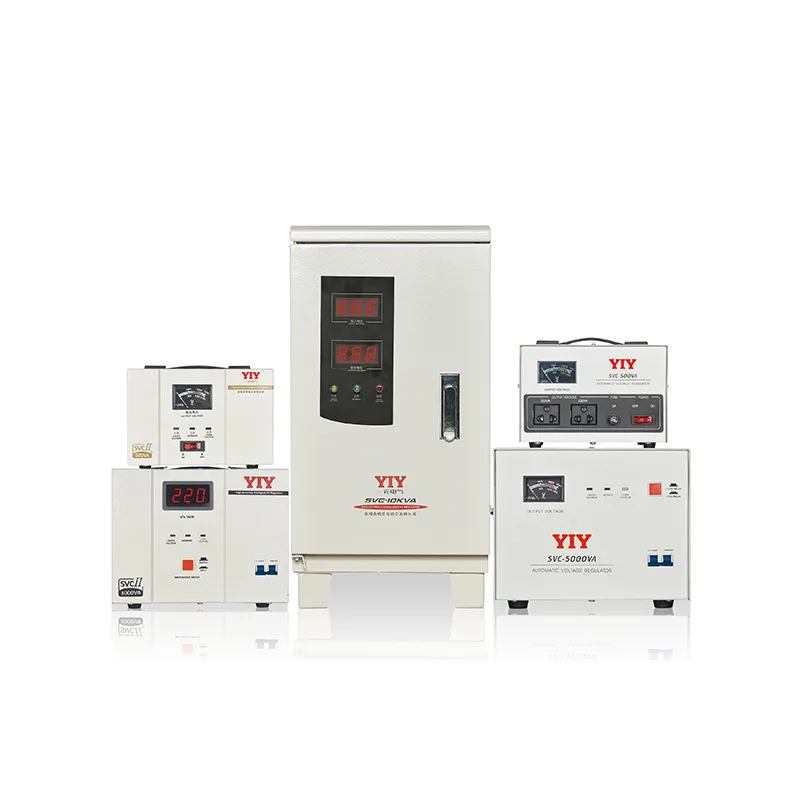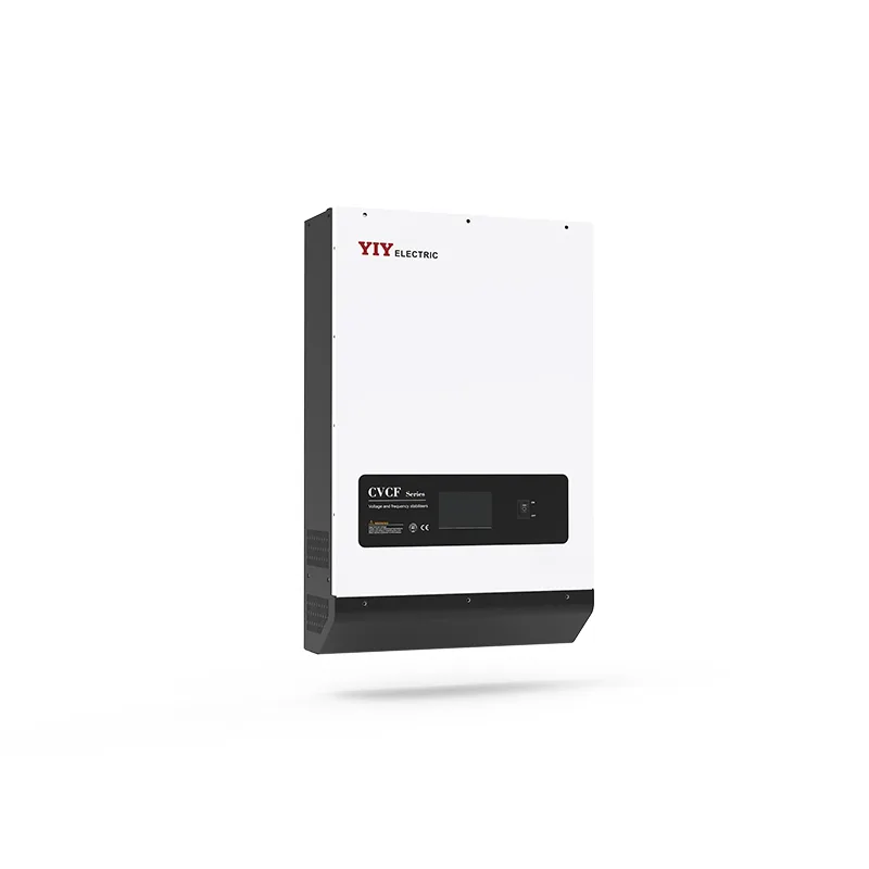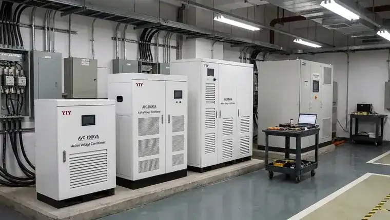
Servo stabilizer in healthcare refers to a voltage regulator that ensures continuous power correction for critical medical equipment. Servo stabilizer application in critical healthcare comes down to one practical question: does the load tolerate stepped voltage correction, or does it require continuous analog regulation? For MRI systems, CT scanners, ventilators, and infusion pumps — where a tap-switching transient mid-procedure is not recoverable — servo topology delivers the correction speed and steady-state accuracy that relay-based units cannot match, at a fraction of what static IGBT converters cost to procure and maintain.
This guide is structured as a technology-selection reference for engineers and procurement teams choosing between servo, relay, and static designs for hospital loads. It covers how each topology behaves under real healthcare conditions, which loads actually justify servo-grade regulation, and the specification checkpoints that matter before you finalize a model or request a quote.
how servo stabilizers regulate voltage
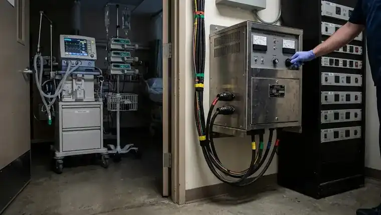
A servo stabilizer corrects voltage through three linked components: a sensing circuit, a servo motor, and a variac (variable autotransformer). The sensing circuit continuously monitors output voltage against a reference setpoint. When deviation is detected, it drives the servo motor, which physically rotates the variac’s carbon brush to inject a compensating voltage — boosting or bucking the supply until output returns to target.
Stepless Correction vs. Relay Switching
The key distinction is how correction happens. Relay-based stabilizers switch between fixed transformer taps — correction jumps in discrete steps, typically ±2.5% or ±5% increments. Each step change introduces a brief transient. Servo topology moves the variac continuously, so correction is analog and uninterrupted. There are no voltage steps, no switching transients, and no dead band where the load sits unprotected between tap positions. For a deeper technical comparison of the correction mechanisms, see how servo stabilizers regulate voltage.
Performance Specifications That Matter
Output precision lands between ±0.5% and ±3% depending on model grade, with industrial servo units typically holding ±1–2% — aligned with 153IEC 60038 standard voltages for equipment voltage tolerance. Response time is ≤1–2 seconds for most supply fluctuations — fast enough to protect imaging equipment and life-support systems from sags that would otherwise trip protection circuits or corrupt calibration cycles.
Why Variable Hospital Loads Favor This Topology
Hospital electrical environments mix inductive loads (MRI gradient coils, motor-driven HVAC, elevator drives) with resistive and electronic loads (CT scanners, ventilators, monitors). This mix creates continuous, unpredictable load swings rather than stable plateaus. Relay stabilizers handle stable loads reasonably well but accumulate wear and introduce transients under frequent switching. Servo correction tracks these fluctuations in real time without discrete steps, making it the preferred topology wherever load profiles are mixed and voltage variation is persistent rather than occasional.
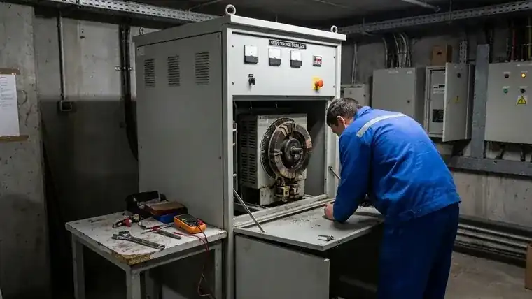
Which Healthcare Loads Actually Need Servo-Grade Servo Stabilizer Application
Not every hospital circuit justifies servo topology. The decision comes down to how the equipment responds to voltage deviation — and whether a stepped correction artifact is acceptable during operation.
Imaging Systems: MRI and CT
MRI gradient coils and RF amplifiers operate within tight voltage windows. According to 6124IEEE 1159 power quality monitoring standard, voltage sags are among the most disruptive power quality events for sensitive electronic equipment — and in MRI, a sag during image acquisition corrupts the scan and forces a restart. CT scanners draw high, variable current during rotation; relay-based stabilizers introduce tap-switching transients precisely when load demand peaks. Both systems require ±1–2% steady-state regulation with no switching artifacts. Servo’s continuous variac correction meets this; relay topology does not.
ICU and Life-Support Equipment
Ventilators and infusion pumps are the clearest case for servo. These loads run continuously, often on dedicated circuits, and their microcontroller-based drive systems are sensitive to both sags and transient spikes. Under the IEC 60601IEC 60601 medical electrical equipment standard, medical devices must maintain safe operation within defined voltage tolerance bands — a relay stabilizer switching between taps introduces a brief voltage step of 2.5–5% that can trigger protection circuits or cause momentary output interruption. In an ICU, that is not recoverable. Operation theater circuits face the same constraint: surgical lighting systems with electronic ballasts and electrosurgical units cannot tolerate stepped correction during a procedure.
Diagnostic and Lab Equipment
Hematology analyzers, PCR machines, and digital pathology scanners are sensitive to micro-fluctuations that relay-type stabilizers miss entirely. These units sit between tap positions during minor supply variation — the dead band where no correction occurs. Servo tracks continuously, so even small deviations within ±5–10% of nominal get corrected before they affect calibration cycles or sensor readings. The same sensitivity profile applies to precision industrial loads — as covered in the Servo Stabilizer For Cnc Machinesservo stabilizer for precision industrial loads guide for CNC machines, where calibration cycles and microcontroller drives face identical voltage sensitivity constraints.
Where a Basic AVR Suffices
Not all hospital loads need servo. Administrative areas, general lighting, HVAC motors, and non-critical ward equipment tolerate relay-based correction without consequence. A basic AVR handles these loads at lower cost and with simpler maintenance. The rule: if the load has a microcontroller, a calibration cycle, or a patient-safety dependency, servo is the right topology. If it doesn’t, a relay AVR is adequate.
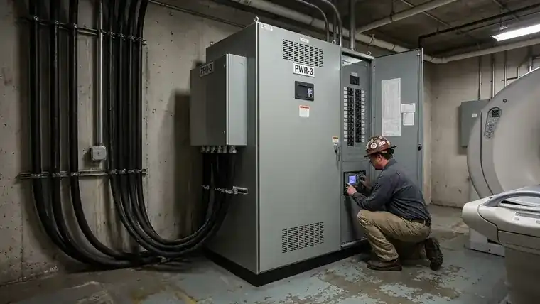
Servo vs. Relay vs. IGBT: Where Each Topology Wins
Three correction topologies dominate the hospital stabilizer market. Each has a distinct performance profile — and the wrong choice for a given load creates problems that no amount of capacity headroom can fix. For a detailed technical breakdown of Stabilizer Voltage Regulator Comparisonservo vs. IGBT technology in modern stabilizer designs, including cost modeling and application fit matrices, see the full comparison guide.
| Topology | Correction Method | Output Precision | Response Time | Relative Cost | Best Fit |
|---|---|---|---|---|---|
| Relay | Tap switching (stepped) | ±2.5–5% per step | Fast (cycles) | Low | Non-critical loads, admin, HVAC |
| Servo | Continuous variac | ±1–3% (±2% typical) | ≤1–2 seconds | Medium | Most hospital departments |
| IGBT (static servo stabilizer) | Power electronics | ±0.5–1% | Sub-cycle | 3–5× servo | Life-support, mission-critical |
Relay: Fast but Stepped
Relay stabilizers switch between fixed transformer taps. The correction is fast — often within a few cycles — but it arrives in discrete jumps of ±2.5% or more. For stable, non-sensitive loads like general lighting, HVAC motors, or administrative equipment, that’s acceptable. For imaging systems or ICU equipment, each tap transition is a transient event. Relay topology is not appropriate for loads with active calibration cycles or microcontroller-based drive systems.
IGBT: Highest Precision, Highest Cost
Static IGBT designs use power electronics to correct voltage within a sub-cycle window, achieving ±0.5–1% output precision with no mechanical components. That performance profile is justified for life-support equipment where even a brief sag is unacceptable — ventilators on dedicated ICU circuits, for instance. The tradeoff is cost: IGBT units typically run 3–5× the price of equivalent servo capacity, plus higher maintenance complexity. For most hospital departments, that premium is not warranted. Note that some vendors market these as “static servo stabilizers” — the static designation refers to the absence of moving parts, not a variant of servo topology.
Servo: The Practical Middle Ground
Servo topology delivers ±2% precision with MCU-based control, continuous variac correction, and no switching transients. It handles the mixed inductive-electronic load profiles typical of imaging suites, operation theaters, and diagnostic labs without the cost burden of IGBT. YIY’s PRO-3 series (1.5KVA–100KVA) and PWR-3 series (45KVA–150KVA) are built around this profile — MCU control, overload protection ≥120%, and motor protection for three-phase hospital loads.
Vendor Positioning
TSI Power focuses specifically on medical, telecom, and outdoor applications — a narrower vertical with deep application expertise in those segments. YIY takes a broader approach: servo, relay, and IGBT topologies across 500VA–3000KVA, with OEM/ODM customization and distribution to 130+ countries. For procurement teams sourcing across multiple hospital departments or geographies, that range matters — one supplier can cover non-critical ward AVRs, imaging-suite servo units, and high-precision IGBT installations under a single qualification process.
Specification Checkpoints Before You Finalize a Model
Sound Voltage Stabilizer Selectionvoltage stabilizer selection starts with six parameters confirmed before the quote stage. Getting them wrong means either undersizing the unit — which trips protection circuits under inrush — or oversizing it, which adds cost and floor space without benefit.
1. Input Voltage Range and Fluctuation Depth
Measure actual supply voltage at the installation point over at least 24 hours, not just nominal. Hospital grids in many markets fluctuate ±15–25% from nominal during peak load periods. Your stabilizer’s input range must cover the worst-case low, not just the average. The PWR-3 Series is built for ultra-low input scenarios — relevant when the incoming supply regularly drops well below standard tolerance.
2. Load kVA with Inrush Headroom
Size at 120–130% of connected load kVA, not nameplate. Imaging equipment draws 3–5× rated current at startup. A CT scanner rated at 30 kVA can pull 90–150 kVA inrush for 2–3 cycles. If your stabilizer’s overload rating doesn’t absorb that, it trips on startup. Both PRO-3 and PWR-3 carry overload protection ≥120%, which handles normal inrush — but the base kVA selection still needs the headroom built in before overload protection kicks in. For broader Voltage Stabilizer Industrial Technical Guideindustrial voltage stabilizer sizing methodology covering inrush calculation across load types, the industrial sizing guide provides the full framework.
3. Phase Configuration and Load Balance
Three-phase hospital loads are rarely balanced. ICU wings, imaging suites, and HVAC systems pull unevenly across phases. The PWR-3 Series (45–150 kVA) supports 100% unbalanced loading — meaning it maintains ±2% output precision even when one phase carries the full load. If your site has significant phase imbalance, this is the spec that matters, not just total kVA.
4. Series Selection as a Sizing Anchor
| Series | Range | Key Fit |
|---|---|---|
| PRO-3 | 1.5–100 kVA | Department-level loads: diagnostic labs, ward circuits, small imaging rooms |
| PWR-3 | 45–150 kVA | Building-level or imaging suite feeds with unbalanced loading |
Both carry MCU control and motor protection for three-phase loads. PRO-3 covers most department-level installations; PWR-3 handles high-capacity feeds where unbalanced loading is the primary constraint.
5. Bypass Switch
A manual bypass switch is non-negotiable in clinical environments. Servo stabilizers require periodic carbon brush inspection — typically every 6–12 months under continuous load. Without a bypass, maintenance means taking the protected circuit offline. In an ICU or imaging suite, that’s not acceptable. Confirm bypass is included or specified as an add-on before finalizing the order.
6. Ambient Conditions and Maintenance Access
Servo stabilizers with variac mechanisms generate heat and require ventilation clearance — typically 300–500 mm on service sides. Confirm the installation space meets the manufacturer’s ambient temperature rating (usually ≤40°C) and that the carbon brush assembly is accessible without moving the unit. Tight electrical rooms in older hospital buildings are a common oversight at the procurement stage.
When to Replace an Old Servo Stabilizer in a Healthcare Setting
An old servo stabilizer that has been running for 8–12 years in a hospital environment presents a different decision than a new installation. The question is whether to service or replace — and the answer depends on what’s degraded.
Carbon brush wear is the most common failure mode. If brush replacement restores output precision to ±2% and the variac winding shows no scoring or hot spots, continued service is reasonable. If the variac winding itself is damaged, or if the MCU control board is no longer supported by the manufacturer, replacement is the better call — repair costs on aging units often approach 40–60% of new unit cost without restoring full performance.
For old servo stabilizer units installed before MCU-based control became standard, the upgrade case is stronger: modern MCU-controlled units offer better protection logic, remote monitoring capability, and tighter output precision than older analog-controlled designs. If the hospital is also expanding load capacity — adding a new imaging suite, for instance — that’s the natural trigger to replace rather than service.
When Servo Is Not the Right Answer
Servo stabilizers are the right call for most hospital departments — but not every load, and not every scenario.
Moving Parts Mean Scheduled Maintenance
The variac mechanism that makes servo correction smooth and continuous is also its main liability: it has moving parts. The carbon brush that rides the variac winding wears down under continuous load. In a hospital environment running 24/7, expect brush inspection every 6–12 months and replacement every 1–2 years. The servo motor itself requires periodic lubrication and alignment checks. This is manageable with a bypass switch and a maintenance schedule — but it’s a real operational cost that static designs don’t carry.
Single Mission-Critical Loads: Consider IGBT or Online UPS
For a single life-support load — one ICU ventilator on a dedicated circuit, one surgical robot — servo’s 1–2 second response window and mechanical correction path may not be the right fit. IGBT stabilizers correct within sub-cycle windows with no mechanical wear. Online UPS systems go further, providing zero-transfer-time switchover and battery backup in a single unit. If the load is singular, patient-critical, and cannot tolerate even a brief correction lag, the cost premium of IGBT or UPS is justified. Servo’s strength is covering mixed, multi-load department circuits — not protecting a single point of failure.
Small Loads Don’t Justify the Cost
For loads under 1 KVA — a bedside monitor, a nurse station PC, a small diagnostic display — a basic relay AVR is sufficient. These loads tolerate stepped correction without consequence, and the cost and maintenance overhead of servo topology adds nothing. Below 1 KVA on non-sensitive equipment, a standard AVR does the job at a fraction of the price.
How YIY Supports Healthcare Servo Stabilizer Projects
YIY’s engineering process starts before model selection — with a load assessment and topology recommendation. The question isn’t just “which servo unit fits?” but whether servo, relay, or IGBT is the right topology for the application in the first place.
Topology Selection, Not Just Product Sales
Most stabilizer suppliers quote a model once you provide kVA and voltage range. YIY’s approach evaluates load type, fluctuation depth, phase balance, and maintenance context before recommending a topology. For a mixed imaging-suite feed, that typically points to servo. For a single mission-critical ICU ventilator, IGBT may be the better call. For non-critical ward circuits, a relay AVR is sufficient and more cost-effective.
PRO-3 and PWR-3: The Healthcare Range
The PRO-3 Series (1.5KVA–100KVA) covers department-level installations — diagnostic labs, imaging rooms, ward circuits — with MCU control, ±2% output precision, overload protection ≥120%, and motor protection for three-phase loads. The PWR-3 Series (45KVA–150KVA) handles building-level feeds and imaging suite infrastructure where ultra-low input tolerance and 100% unbalanced loading capability are the primary constraints.
Both series carry ISO 9001:2015 and CE certification, and have been deployed across 130+ countries — including markets where hospital grid quality is highly variable and stabilizer performance under real-world conditions matters more than datasheet specs.
OEM/ODM for Facility-Specific Requirements
For projects with non-standard enclosure requirements, custom input ranges, or facility-specific protection configurations, YIY supports OEM/ODM customization. This is relevant for large hospital groups or EPC contractors sourcing across multiple sites under a single specification.
Request a technical review to confirm whether servo, relay, or IGBT is the right fit for your application — and which model covers the load profile, site conditions, and maintenance context you’re working with.
Frequently Asked Questions
When is servo stabilizer application necessary in a hospital?
Servo stabilizer application becomes necessary when the load has a calibration cycle, a microcontroller-based drive, or a direct patient-safety dependency. MRI gradient coils, CT scanners, ventilators, and infusion pumps all qualify. These systems cannot tolerate the stepped voltage transitions that relay-based AVRs produce — a 2.5–5% tap-switching transient can trigger protection circuits or corrupt an active scan. If the equipment runs continuously and a brief voltage artifact is not recoverable mid-operation, servo topology is the right call.
How should a servo stabilizer be sized for healthcare equipment?
Size at 120–130% of connected load kVA, not nameplate. Imaging equipment draws 3–5× rated current at startup — a 30 kVA CT scanner can pull 90–150 kVA inrush for 2–3 cycles. The stabilizer’s overload rating must absorb that without tripping. For three-phase servo stabilizer ICU feeds with uneven load distribution across wings and imaging suites, confirm the unit supports 100% unbalanced loading. The PWR-3 Series (45–150 kVA) is built for exactly this scenario.
What should buyers evaluate before choosing a servo stabilizer for critical loads?
Six checkpoints matter: actual input voltage range measured over 24 hours (not just nominal), load kVA with inrush headroom, phase balance at the installation point, bypass switch availability for maintenance, ambient temperature and ventilation clearance, and whether servo is even the right topology. For a single mission-critical ICU ventilator, IGBT or online UPS may be a better fit. For mixed department feeds, servo is typically the practical middle ground.
Is servo better than IGBT for hospital applications?
It depends on the load. Servo delivers ±1–3% output precision with continuous variac correction — sufficient for imaging suites, diagnostic labs, and most ICU circuits. IGBT corrects within sub-cycle windows at ±0.5–1% precision, with no mechanical wear, but costs 3–5× more per equivalent kVA. For multi-load department feeds, servo’s cost-to-performance ratio is hard to beat. For a single life-support load where even a 1–2 second correction lag is unacceptable, IGBT is the right answer.
When should an old servo stabilizer in a hospital be replaced?
Replace rather than service when: the variac winding shows scoring or hot spots beyond brush wear, the control board is no longer manufacturer-supported, or repair costs exceed 40–60% of new unit cost. If the unit predates MCU-based control, the upgrade to modern precision and protection logic is typically worth the capital cost — especially if load capacity is also expanding.
Final Thoughts
Servo fits most hospital departments where ±2% precision and cost efficiency matter — imaging suites, diagnostic labs, ICU circuits, and operation theaters all fall into this category. IGBT is the right call for a single mission-critical point where even a 1–2 second correction window is unacceptable. Relay AVRs handle non-sensitive loads at lower cost and simpler maintenance. The right answer depends on load type, site conditions, phase balance, and your team’s maintenance capacity — not on a default topology assumption.
If you’re finalizing a specification or evaluating whether servo, relay, or IGBT fits your application, request a technical review with YIY’s engineering team. Bring your load profile and site conditions — that’s where the real selection work happens.
—
About YIY
Zhejiang Yiyen Holding Group Co., Ltd. (YIY) is a professional voltage stabilizer manufacturer with 16+ years of experience. With a 30,000sqm modern facility and an annual production capacity of 1,000,000+ units, our products are exported to 130+ countries. We provide OEM/ODM customization services and are ISO 9001:2015 certified, committed to delivering stable and reliable voltage protection solutions to global customers.
Contact Us
Email: yiyen at yiyen.com
Phone/WhatsApp: +86 13587452904
Website: https://www.yiyavr.com/