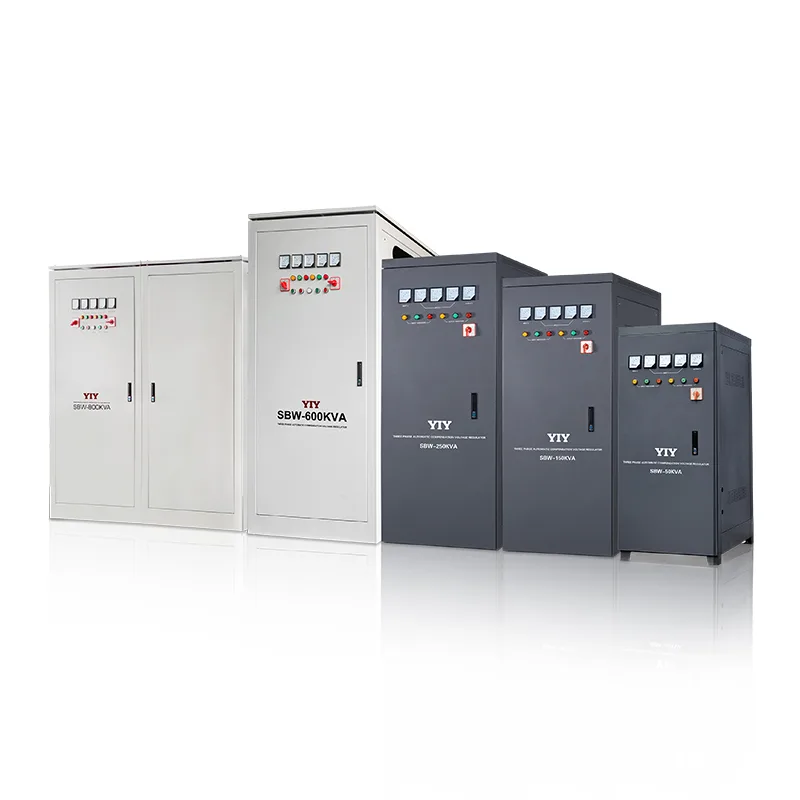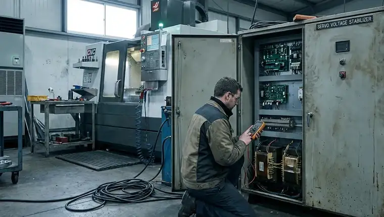
Unplanned voltage drift doesn’t just trigger control panel alarms; it degrades sensitive industrial loads, corrupts data logs, and forces costly process interruptions. When a persistent stabilizer output problem emerges, facility managers face a critical procurement tradeoff: patch an aging electromechanical system, upgrade to a precision servo topology, or deploy static solid-state correction. Choosing incorrectly means paying twice for hardware while risking accelerated equipment failure. The right decision hinges on matching correction speed, precision tolerance, and local grid volatility to your operational baseline.
This evaluation framework maps the technical selection criteria needed to navigate those tradeoffs. By understanding the core mechanics of a modern servo voltage stabilizer, we break down load compatibility requirements, compare response behaviors across stabilization architectures, and outline the specification checkpoints that must be verified before final vendor approval. This guide equips you with a data-backed decision path to align your power protection strategy with long-term uptime targets.
What Stabilizer Output Instability Means for Industrial Loads
Voltage instability isn’t merely a blinking warning light; it is a direct threat to facility uptime and capital equipment longevity. When a stabilizer output problem goes unaddressed, the resulting power quality degradation forces sensitive systems into protective shutdowns or accelerates premature thermal wear cycles. The root causes typically fall into two distinct operational categories: external grid extremes and internal control degradation.
Exceeding the Compensation Threshold
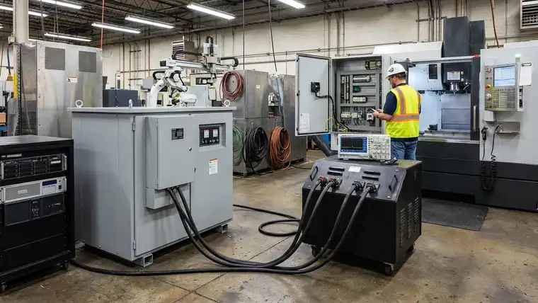
Every industrial voltage regulator operates within a defined input tolerance band, frequently capped at ±10% per international manufacturing standards. When grid sags or spikes breach this compensation range, the autotransformer and motor mechanism physically cannot maintain the target output voltage. The control board defaults to raw pass-through or triggers a hard lockout, instantly exposing downstream assets to unregulated line swings. This scenario frequently manifests as a stabilizer output less than input condition, leaving critical machinery underpowered during peak production hours.
Control-Side Degradation and Silent Failures
Internal component fatigue triggers output drift long before visible alarms appear. Faulty switching relays stick during phase corrections, while prolonged thermal cycling degrades critical PCB capacitors and timing circuits. Coupled with gradual voltage sensor drift, these micro-failures corrupt the MCU’s real-time feedback loop, causing the unit to apply inaccurate corrections to stable loads. Understanding why servo stabilizer output drifts under heavy load often starts here: worn carbon brushes lose consistent contact with the autotransformer windings, creating intermittent resistance spikes that confuse the control algorithm.
Cascading Impact on Critical Infrastructure
The downstream damage scales directly with load sensitivity across your facility. Precision CNC spindles and servo-driven robotics suffer from positional inaccuracies and premature bearing wear, while telecom infrastructure experiences packet loss and router reboots. Continuous exposure to minor output instability compounds across automated production lines, transforming localized voltage drift into systemic throughput bottlenecks. Proactive intervention prevents localized power anomalies from reflecting upstream, effectively neutralizing cascading grid failures and protecting primary distribution transformers.
When to Choose Servo Over Relay or Static Topologies
Selecting the correct voltage correction architecture requires matching regulation mechanics directly to your load’s tolerance window. Not all industrial environments require sub-1% accuracy, and overspecifying hardware drains capital without delivering measurable ROI. The table below outlines the core performance characteristics that dictate topology selection:
| Topology | Correction Method | Output Accuracy | Response Time | Ideal Application Profile | Maintenance Frequency |
|---|---|---|---|---|---|
| Servo Voltage Stabilizer | MCU-controlled motor sweeps carbon brush on autotransformer | ±0.5% to ±3% | ≤ 1–2 seconds | Precision CNC, medical imaging, test labs, automated manufacturing | Quarterly brush inspection, annual PCB calibration |
| relay voltage stabilizer | Electromagnetic relays switch discrete transformer taps | ±5% to ±10% | 0.5–1 seconds (stepped) | HVAC arrays, general workshop lighting, non-critical pumps, residential blocks | Annual contact cleaning, relay continuity testing |
| Static / IGBT Regulator | Semiconductor switching (thyristor/IGBT) injects compensating voltage | ±1% to ±3% | < 20 milliseconds | Data centers, semiconductor fabs, high-frequency trading servers | Minimal mechanical wear; periodic thermal paste/fan replacement |
The Micro-Adjustment Advantage
Continuous grid drift makes servo mechanics the only viable solution for high-sensitivity loads. Precision CNC spindles and semiconductor test benches cannot tolerate voltage sags during relay step-changes. Real-time feedback loops continuously map input variance against factory requirements, allowing servo units to prevent micro-voltage hunting and cumulative thermal stress in sensitive drive electronics. For detailed insights into securing CNC machine power protection, evaluating the mechanical sweep characteristics is essential.
Where Relay or Static Remain Cost-Effective
Discrete stepping correction remains highly acceptable for bulk industrial infrastructure. Facilities powering commercial HVAC arrays, heavy-duty conveyors, or standard workshop lighting rarely require tighter than ±5% tolerance. A standard relay voltage stabilizer delivers proven uptime at minimal capital expenditure, provided the load tolerates brief microsecond interruptions during tap switching. Static designs excel instead when ultra-fast spike suppression outweighs stepless accuracy, particularly in networks prone to rapid inductive switching. Procurement teams should calculate total cost of ownership rather than upfront hardware pricing when evaluating correction topologies. For a deeper dive into architecture selection, consult our comprehensive relay vs servo vs IGBT comparison guide.
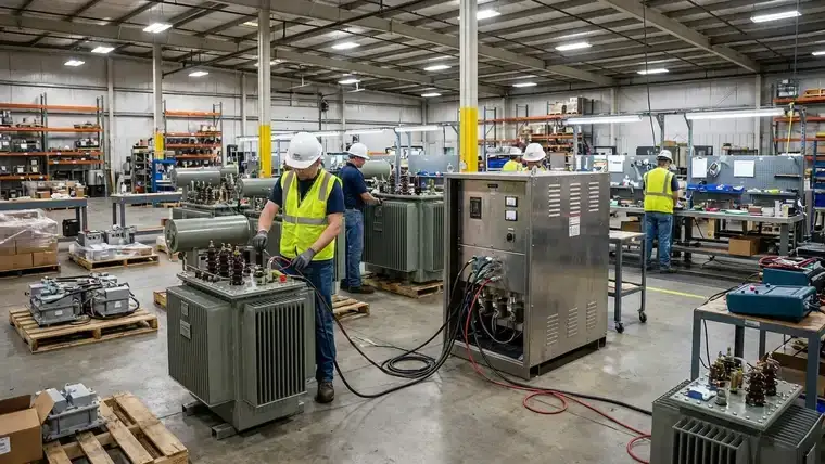
How Industrial Servo Stabilizers Maintain Voltage Precision
Understanding how voltage stabilizers work is critical when diagnosing persistent regulation failures. Industrial servo voltage regulators depend on a tightly coupled electromechanical feedback loop to neutralize line fluctuations. Instead of stepping through fixed voltage taps, the system relies on continuous physical movement to deliver sub-second accuracy.
The Continuous Correction Cycle
An integrated MCU constantly monitors incoming line voltage, processing real-time RMS data against a factory-calibrated reference point. When a deviation is detected, the controller dispatches rapid control signals to a high-torque servo motor governed by advanced closed-loop servo control systems. This motor physically sweeps a heavy-duty carbon brush along the exposed copper winding of a precision autotransformer.
The mechanical sweep directly alters the transformer’s active winding length. This real-time turns ratio adjustment continuously injects or subtracts voltage, effectively closing the compensation gap with stepless precision. Because the brush tracks analog gradients rather than digital switches, the output curve remains completely smooth, eliminating transient micro-spikes. A thorough servo voltage stabilizer maintenance checklist should always prioritize brush wear measurement and carbon dust extraction during this cycle.
Standards Compliance and Hybrid Resilience
This architecture operates within strict engineering boundaries aligned with IEC 60038 global voltage standards. Industrial units are engineered to absorb typical ±10% input tolerance thresholds, only triggering internal safety lockouts when extreme grid excursions breach this verified compensation band.
The hybrid electro-mechanical topology consistently outperforms purely electronic IGBT switching in highly unstable grid environments. While solid-state designs struggle with electromagnetic interference and thermal runaway during prolonged sags, servo units absorb massive grid swings by physically redistributing magnetic flux across the transformer core. This design naturally prioritizes thermal stability, component longevity, and output purity over brute-force switching speeds.
Specification and Maintenance Checkpoints Before Purchase
Technical buyers must validate design parameters well beyond headline kVA ratings and basic marketing claims. Implementing a rigorous pre-purchase checklist prevents hidden operational expenses and guarantees that the deployed architecture withstands real-world facility volatility.
Critical Sizing and Environmental Factors
Mapping the operational envelope demands exact alignment with historical grid telemetry logs. Verify the maximum input voltage compensation window against site-specific sag records to ensure the autotransformer absorbs extreme regional dips reliably. Ignoring localized grid volatility forces the unit into continuous saturation modes that accelerate winding degradation. Calculate true power demands by plotting inductive motor start currents against the unit’s continuous thermal rating. Capacitive switching surges require identical headroom margins to prevent sudden overheating during peak shifts. Always apply strict ambient temperature derating curves for enclosed panels, and explicitly mandate external manual bypass breakers to eliminate production halts during scheduled service intervals.
Long-Term Maintenance Realities
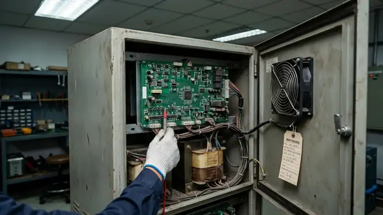
Electromechanical regulation depends entirely on predictable, documented upkeep cycles. Secure binding vendor agreements on carbon brush replacement intervals to guarantee uninterrupted line protection. Standardize hot-swap procedures across your maintenance schedule to avoid costly emergency shutdowns. Effective servo stabilizer troubleshooting begins with auditing the access panels: isolate the internal control cabinet for unobstructed PCB diagnostic access before approving the final quotation. Isolating fault logs without dismantling the main chassis saves dozens of engineering hours annually. Furthermore, validate forced-air cooling capacities against high-harmonic environments to prevent thermal runaway during sustained correction cycles.
Quality Validation Markers
Manufacturing pedigree and pre-dispatch testing protocols dictate long-term regulation consistency across unstable networks. Procure exclusively from vendors holding valid ISO 9001:2015 design certification, which enforces strict component traceability and automated assembly controls. Demand comprehensive Factory Acceptance Testing (FAT) reports that mathematically verify dynamic load response. Require signed documentation proving output stability under 120% overload simulation before shipment. Overlooking these validation steps forces the internal feedback loop into constant overcompensation. This architectural oversight directly triggers post-installation output instability, making future automatic stabilizer repair scenarios far more complex and expensive.
Aligning YIY Solutions to Your Application Requirements
Theoretical sizing frequently fails without historical grid telemetry and accurate facility duty-cycle mapping. YIY bridges this critical gap by mandating comprehensive pre-installation load profiling and localized grid data analysis before final hardware fabrication. This rigorous validation protocol systematically eliminates hidden capacity bottlenecks and prevents fundamental topology mismatches that trigger chronic voltage drift.
Instead of relying on generic manufacturer datasheets, our centralized engineering review translates raw operational metrics directly into a verified electrical architecture. We rigorously map motor inrush currents, harmonic distortion profiles, and strict ambient derating curves against your facility’s continuous thermal rating. This structured consultation pathway transforms abstract procurement requirements into deployment-ready validation blueprints, eliminating costly trial-and-error sizing. When operators report persistent alarm states, learning exactly how to fix h1 error in ac stabilizer units requires precise voltage threshold mapping, which our configuration tools automate.
Scalable Deployment and Site-Specific Customization
Our established deployment footprint currently spans 130+ countries, delivering precision voltage regulation from compact 0.5KVA control modules to massive 3000KVA industrial distribution networks. Every manufacturing cycle operates under ISO 9001:2015 quality management standards and strict CE compliance frameworks, guaranteeing seamless integration into highly regulated power infrastructures across diverse international markets.
Complex industrial facilities routinely demand modified mechanical form factors or hardened enclosure ratings to withstand corrosive chemical environments. Through dedicated OEM/ODM customization, our application engineers actively recalibrate autotransformer winding densities, forced-air cooling capacities, and programmable control matrices to match extreme site constraints. This targeted engineering adaptability guarantees your selected power architecture survives brutal grid volatility without triggering expensive post-deployment retrofits.
Transitioning from theoretical evaluation to active implementation permanently removes financial guesswork from critical infrastructure procurement projects. Aligning validated component specifications with verified operational dynamics ensures uninterrupted, precision voltage regulation across your most sensitive production lines while maintaining strict compliance with international electrical safety codes.
Frequently Asked Questions
What should buyers evaluate before choosing stabilizer output problem solutions?
Buyers must first audit downstream load sensitivity and historical grid telemetry. High-precision CNC spindles and semiconductor test benches demand continuous servo regulation to maintain tight output accuracy, eliminating micro-spikes that corrupt control loops. Mapping input voltage deviations against factory baselines prevents hidden saturation modes and ensures the architecture absorbs regional grid extremes reliably.
When is a stabilizer output problem necessary to address?
Active intervention becomes critical when persistent voltage drift forces sensitive assets into protective shutdowns or accelerates premature bearing wear. If aging relay units frequently trip during phase transitions or cannot maintain tight tolerance under heavy inductive loads, transitioning to a stepless servo topology is mandatory to stabilize operations and eliminate costly line stoppages.
How should stabilizer output problem troubleshooting be prioritized?
Never rely on headline kVA ratings or assume a full hardware replacement is required. Engineering teams should first plot motor inrush currents against the system’s continuous thermal rating and secure headroom for switching surges. Next, mandate ISO 9001:2015 compliance validation, check forced-air cooling for harmonic-rich environments, and verify manual bypass breakers to eliminate production halts during maintenance intervals. Most drift issues resolve through carbon brush realignment and sensor recalibration before major component replacement is considered.
Final Thoughts
Solving a persistent stabilizer output problem isn’t about purchasing over-spec hardware; it’s about strictly aligning correction topology with verified grid telemetry and load tolerance windows. While discrete relay stepping remains cost-effective for bulk infrastructure, precision automation demands the continuous, stepless correction only a closed-loop servo architecture delivers. Skipping site-specific validation guarantees repeated micro-shutdowns and accelerated component fatigue. Before finalizing procurement, request a technical configuration review with YIY engineering. We will audit your operational baselines, confirm sizing margins, and specify the exact topology required to permanently eliminate output instability.
About YIY
Zhejiang Yiyen Holding Group Co., Ltd. (YIY) is a professional voltage stabilizer manufacturer with 16+ years of experience. With a 30,000sqm modern facility and an annual production capacity of 1,000,000+ units, our products are exported to 130+ countries. We provide OEM/ODM customization services and are ISO 9001:2015 certified, committed to delivering stable and reliable voltage protection solutions to global customers.
Contact Us
Email: yiyen@yiyen.com
Phone/WhatsApp: +86 13587452904
Website: https://www.yiyavr.com/
If you found this article helpful, contact us for a sizing review or customized solution.